404A965H01
Description
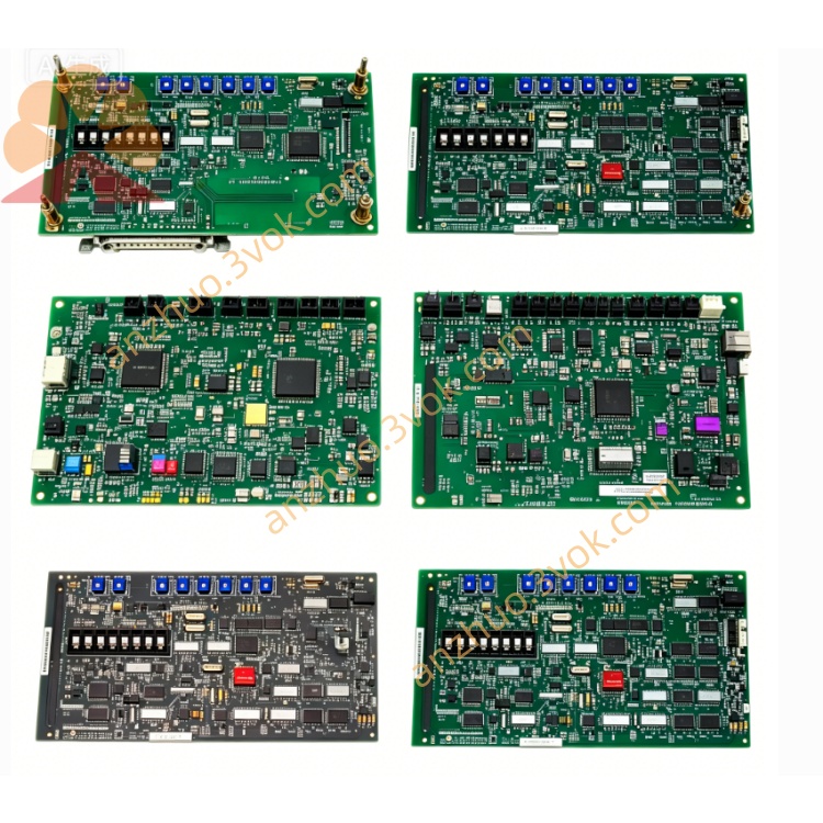
1. Product Introduction
2. Technical Specifications
Channels: 16 independent isolated digital outputs (sourcing/sinking)
Output Type: 24 VDC logic, 0.5 A per channel (max 2 A total)
Isolation Voltage:
Channel to backplane: 1500 VAC, 1 minute
Channel to channel: 500 VAC, 1 minute
Load Voltage Range: 18–30 VDC (nominal 24 VDC)
Response Time: ≤ 8 ms (typical)
Power Supply: 24 VDC ±10% (from DCS backplane)
Max Power Consumption: ≤ 5 W
Operating Temperature: 0 °C to +55 °C
Storage Temperature: −20 °C to +70 °C
Relative Humidity: 5%–95%, non‑condensing
Key Features: Hot‑swappable; fail‑safe (OFF) on power/communication loss
LED Indicators: Green (PWR), Red (FAULT), Yellow (CH1–CH16 status)
Physical: Single‑slot module; approx. 220 × 30 × 250 mm, 1.2 kg
3. Application Fields
Power Generation: Thermal/nuclear power plant valve control, pump motor start/stop, interlock relay driving.
Petrochemical: Solenoid valves, emergency shutdown (ESD) devices, motor starter coils.
Water Treatment: Dosing pumps, drain valves, aeration equipment control.
General Process Industries: Metallurgy, pulp & paper, cement, and other high‑reliability discrete output applications.
4. Installation & Wiring
Pre‑installation: Ensure the DCS cabinet is de‑energized before installation.
Module Insertion: Insert the module into an available I/O slot; the backplane connector engages automatically.
Hot Swap: Verify the system permits online replacement (Ovation/WDPF compatible).
Field Wiring:
Connect load positive to OUT terminal, load negative to COM terminal per channel.
Maintain isolation between field wiring and backplane cabling.
Secure Connections: Avoid over‑torqueing terminals; ensure wiring is neat and secure.
5. Operation & Diagnostics
Power‑on: Green PWR LED illuminates when 24 VDC is supplied.
Channel Status: Yellow LED = output ON; LED off = output OFF.
Fault Indication: Red FAULT LED = detected fault (e.g., communication loss, overcurrent, short circuit, or channel failure).
Diagnostics: The module reports channel‑level status to the DCS for alarm and maintenance logging.
6. Maintenance & Safety
Preventive Maintenance: Inspect connections annually; test output channels for accuracy and load capacity.
Safety:
Disconnect all power before servicing.
Do not exceed rated output voltage/current.
Operate within specified temperature/humidity limits.
7. Product Status
Lifecycle: End‑of‑Life (EOL); original manufacturing discontinued.
Availability: Refurbished and used units offered as spare parts; typical warranty 6–12 months.
Compatibility: Fully compatible with Ovation, WDPF, and Q‑Line DCS systems。
Get a Quote