Bently Nevada Printed Wiring Assembly Specification
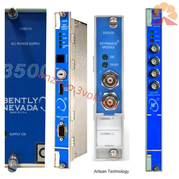
PWA72202-01 is original factory printed wiring assembly serving as core internal main circuit board for Bently Nevada 3500/20 Rack Interface Module within industry-standard 3500 series rack-based turbomachinery condition monitoring and protection system, fully compliant with API 670 rotating machinery protection specification, CE EMC electromagnetic compatibility certification and North American industrial electrical safety standards for fixed cabinet installation in power, petrochemical and heavy industry control rooms. This PWA acts as central bus relay hub responsible for bidirectional data exchange between all monitor modules inserted in 3500 rack slots and rack main control circuit, realizing unified scheduling of vibration, axial displacement, rotational speed and temperature measurement data collected from 3300 series eddy-current proximity probes, Velomitor velocity pickups and acceleration transducers. After receiving analog and digital measurement signals from each channel monitor board, the assembly completes signal sorting, protocol conversion, transient data buffering and fault code aggregation, then transmits integrated rack operating information to upper configuration software, DCS and PLC control systems via front-panel communication interface. Meanwhile, it distributes rack bus power and unified timing clock signal to all slave monitor modules installed inside the rack; once any module or external sensor circuit triggers pre-defined alert or trip threshold, onboard logic forwards interlock instruction to corresponding relay output modules to execute safety shutdown protection for large rotating equipment including steam turbines and centrifugal compressors. Every finished PWA72202-01 undergoes full bus communication simulation test, continuous powered burn-in aging and high-voltage dielectric withstand inspection before factory delivery to eliminate hidden manufacturing defects from component deviation and PCB production flaws.
Description
Bently Nevada Printed Wiring Assembly Specification
1. Product Overview
PWA72202-01 is original factory printed wiring assembly serving as core internal main circuit board for Bently Nevada 3500/20 Rack Interface Module within industry-standard 3500 series rack-based turbomachinery condition monitoring and protection system, fully compliant with API 670 rotating machinery protection specification, CE EMC electromagnetic compatibility certification and North American industrial electrical safety standards for fixed cabinet installation in power, petrochemical and heavy industry control rooms. This PWA acts as central bus relay hub responsible for bidirectional data exchange between all monitor modules inserted in 3500 rack slots and rack main control circuit, realizing unified scheduling of vibration, axial displacement, rotational speed and temperature measurement data collected from 3300 series eddy-current proximity probes, Velomitor velocity pickups and acceleration transducers. After receiving analog and digital measurement signals from each channel monitor board, the assembly completes signal sorting, protocol conversion, transient data buffering and fault code aggregation, then transmits integrated rack operating information to upper configuration software, DCS and PLC control systems via front-panel communication interface. Meanwhile, it distributes rack bus power and unified timing clock signal to all slave monitor modules installed inside the rack; once any module or external sensor circuit triggers pre-defined alert or trip threshold, onboard logic forwards interlock instruction to corresponding relay output modules to execute safety shutdown protection for large rotating equipment including steam turbines and centrifugal compressors. Every finished PWA72202-01 undergoes full bus communication simulation test, continuous powered burn-in aging and high-voltage dielectric withstand inspection before factory delivery to eliminate hidden manufacturing defects from component deviation and PCB production flaws.
2. Core Functional Characteristics
This multi-layer FR-4 industrial printed wiring assembly integrates proprietary rack bus control circuit, multi-channel data buffer network, onboard system clock generation unit, full-range module loop fault diagnosis circuit, multi-stage surge suppression protection components and ambient temperature drift compensation network to realize comprehensive rack backplane management and system diagnostic functions for complete 3500 monitoring framework. First, isolated digital and analog routing layout separates high-speed internal rack bus and low-frequency sensor signal transmission paths, effectively restraining ground loop interference and electromagnetic noise induced by nearby variable-frequency drives and high-power motor startup under complex industrial electromagnetic surroundings to guarantee stable long-term data transmission without frame loss or signal distortion. Second, built-in independent clock oscillator circuit provides unified synchronous timing reference signal for all inserted monitor modules, ensuring consistent sampling frequency of multi-channel field measurement data and improving the accuracy of vibration spectrum analysis and mechanical fault diagnosis. Third, real-time continuous module status detection circuit automatically scans communication and power supply status of every slot-installed monitor; abnormal module offline, power loss or internal circuit failure will generate standardized NOT OK fault codes transmitted via communication bus for remote alarm display on centralized monitoring host without on-site manual troubleshooting. Fourth, passive distributed temperature compensation design offsets component parameter variation caused by cabinet internal temperature rise from equipment heat dissipation and seasonal ambient fluctuation, stabilizing bus communication precision and power distribution stability across full rated working temperature range. Fifth, transient voltage suppression diodes and RC absorption loops are laid out on power input and external communication terminals to absorb instantaneous surge voltage from lightning induction and power grid switching spike, preventing core control IC chips from overvoltage breakdown damage under unstable industrial power supply conditions.
3. Mechanical Structure and Construction Details
PWA72202-01 adopts customized outline dimension precisely matching standard slot space of Bently 3500 series instrument rack, with pre-reserved fixed mounting holes distributed along PCB edge for reliable screw locking inside metal module housing, enabling the assembly to withstand long-term cyclic mechanical vibration generated by adjacent running turbomachinery and avoid component desoldering or poor contact failure of edge connectors. The substrate applies high-grade multi-layer FR-4 base material with full-area continuous ground copper foil layer to enhance internal electromagnetic shielding and reduce inter-layer signal crosstalk among multi-channel bus traces; thickened copper wiring on main power supply and core high-speed bus paths improves overcurrent resistance and passive natural heat dissipation efficiency during uninterrupted continuous energization and ambient temperature variation. All onboard industrial-grade precision resistors, low-loss film capacitors, dedicated bus processing chips and timing crystal components adopt original factory designated standard spare parts; component soldering is finished by automated wave soldering production followed by selective manual spot inspection to screen cold solder, virtual solder and bridging solder hidden risks. After complete component assembly, entire PCB surface is coated with solvent-resistant three-proof conformal coating to resist erosion from floating industrial dust, lubricating oil mist and weak corrosive volatile chemical vapor accumulated inside closed control cabinet, slowing down copper trace oxidation and component pin corrosion under high-humidity and oil-rich working surroundings near turbine and compressor units. Standard gold-plated edge connector terminals are reserved on one board side for direct docking with 3500 rack internal backplane bus, while front-side welded pins connect with module front panel status indicator lamps including OK, TX and RX status lights; finished bare printed wiring assembly is packed with anti-static vacuum plastic bag at factory to avoid electrostatic breakdown damage during warehouse storage and cross-region logistics transportation.
4. Detailed Electrical Technical Parameters
The wiring assembly is designed for standard rack DC power supply of 3500 system, rated nominal input working voltage is +24VDC, total average power consumption under full-load full-slot module installation operating condition is controlled below 4.5W. It complies with exclusive Bently proprietary internal rack bus communication protocol and maintains full compatibility with all series 3500 monitor modules including proximity monitor, velocity vibration monitor, temperature monitor, keyphasor speed monitor and relay output module, supporting seamless bidirectional data transmission between rack internal hardware and upper computer configuration software. Internal bus signal conversion linearity error after factory standard calibration is controlled better than ±0.9% within effective data transmission scope. Insulation resistance between power input terminal and communication bus terminal exceeds 220MΩ under 500VDC dielectric withstand voltage test, and isolation voltage between internal analog auxiliary circuit and digital bus circuit reaches 1500VDC to block cross-conduction of leakage current between different functional circuits. Built-in surge protection structure can withstand instantaneous common-mode impulse voltage up to 2100V induced by grid transient fluctuation and lightning coupling interference to protect core internal circuit from burnout under unexpected abnormal overvoltage impact. Standardized digital fault signal is output via dedicated front-panel communication terminal when any inserted monitor module appears abnormal working state for upper DCS and centralized monitoring system remote fault collection and alarm prompting.
5. Environmental Operating Specifications
Rated continuous long-term fixed cabinet installation working ambient temperature range is 0°C ~ +60°C; permissible short-duration transient operating temperature extends from -32°C ~ +73°C during temporary cabinet heat dissipation failure or extreme seasonal ambient temperature fluctuation. Safe spare storage temperature range for unused spare circuit boards is -40°C ~ +85°C inside dry, dustproof enclosed warehouse free of corrosive liquid splash and toxic chemical vapor erosion. Applicable working relative humidity scope is 5%RH~93%RH under strict non-condensing environmental condition, well adapting high-humidity coastal petrochemical plant control room and offshore oil platform cabinet installation scenarios. Finished PCB completes standardized industrial vibration reliability certification test and can endure continuous mechanical vibration of 10Hz~1500Hz frequency range during product transportation and on-site module disassembly without copper trace cracking and component falling-off failure. The three-proof protective coating on board passes anti-dew and anti-oil mist reliability verification to adapt severe cabinet surroundings filled with steam and lubricant volatile vapor near large turbomachinery equipment. When installed inside Class I and Class II explosive hazardous area cabinets, matched intrinsic safety barrier components must be added on front-end external communication cable side complying with local regional explosion-proof electrical regulatory standards and intrinsic safety wiring specification requirements.
6. Compatible Equipment and Application Scope
PWA72202-01 serves as exclusive original core printed wiring assembly for Bently Nevada 3500/20 rack interface module, fully compatible with standard 3500 series instrument rack chassis, all specifications of 3500 series monitor modules, mainstream 3300 series eddy-current proximity probes, Velomitor velocity pickups, piezoelectric acceleration transducers and corresponding extension signal cables of different customized lengths. System bus parameter configuration, communication rate adjustment and module slot enable/disable setting are all realized via upper computer configuration software instead of onboard hardware jumper modification, seamlessly matching conventional centralized monitoring host, field alarm relay modules and mainstream DCS/PLC communication cards widely used in traditional industrial control sites. Main applicable industrial fields include thermal power generation, onshore and offshore oil & gas exploitation, petrochemical refining, coal chemical processing and heavy metallurgy industry, functioning as core bus scheduling component for comprehensive vibration, axial displacement and rotational speed monitoring protection system of large steam turbine generator units, centrifugal compressors, boiler induced draft fans and feedwater pump sets. Converted real-time digital monitoring data is transmitted to upper centralized monitoring system for on-site numerical display, historical operating data recording and abnormal mechanical fault early warning, and system protection threshold can be modified via upper configuration software according to actual unit startup and shutdown operating condition variation to ensure reliable whole-set equipment safety management.
7. Factory Quality Control and Warranty Regulation
Each individual PWA72202-01 undergoes multiple mandatory pre-delivery factory inspection items including full-range multi-slot bus communication simulation test with standard master signal source, power supply fluctuation stability test, module offline fault function verification, high-low temperature alternating cycling aging test and insulation withstand voltage inspection to screen out inherent manufacturing defects before formal factory outbound shipment. Original manufacturer limited warranty period lasts twelve consecutive months starting from formal product delivery date to end user; free repair or replacement service is available for products confirmed with inherent factory production defects when installed and operated within rated environmental parameters and standardized wiring requirements during valid warranty term. Any product damage resulting from unauthorized onboard component modification, incorrect field power supply wiring, artificial mechanical collision impact, corrosive liquid immersion and long-term continuous over-temperature operation exceeding specified working limit scope is excluded from official warranty coverage, and all corresponding maintenance and component replacement expenses shall be fully borne by end user.
Get a Quote