Bently Nevada 125680-01 I/O Termination Module Product Specification
125680-01 is a dedicated rear termination board engineered to match the Bently Nevada 3500/45 Differential Expansion Monitor front card within the 3500 series turbomachinery protection and condition monitoring system, manufactured to original US factory specifications and compliant with API 670 international standards for critical rotating machinery safety supervision. Mounted onto the rear of a standard 3500 instrument rack at the slot position corresponding to its paired front differential expansion monitor module, this rear I/O unit serves as the exclusive physical wiring interface for LVDT-type differential expansion transducers installed on steam turbines and heavy rotary equipment. It isolates field sensor cabling from the precision signal processing circuitry on the front monitor card to minimize on-site electromagnetic interference introduced by long-distance field cables and adjacent high-current power wiring. The printed circuit board is covered with industrial-grade conformal coating to defend against cabinet dust, scattered lubricant mist, intermittent condensation and mild corrosive volatile gas, enabling stable long-term deployment inside control cabinets for thermal power, petrochemical, coal chemical, metallurgy and onshore & offshore oil and gas production facilities.
Description
Bently Nevada 125680-01 I/O Termination Module Product Specification
1. General Overview
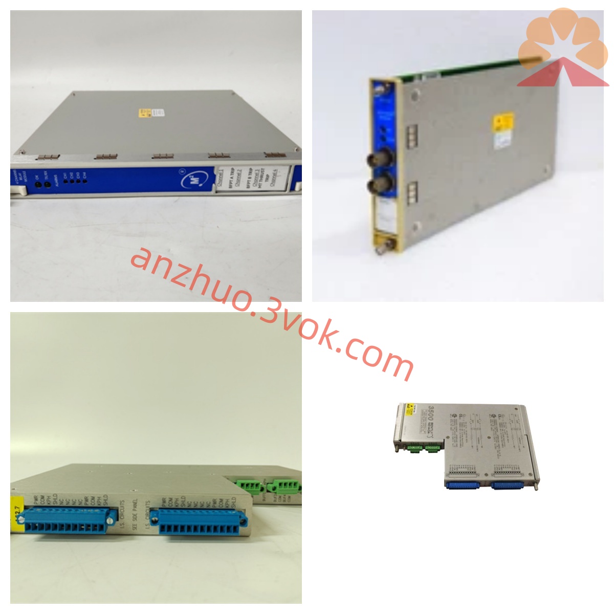
125680-01 is a dedicated rear termination board engineered to match the Bently Nevada 3500/45 Differential Expansion Monitor front card within the 3500 series turbomachinery protection and condition monitoring system, manufactured to original US factory specifications and compliant with API 670 international standards for critical rotating machinery safety supervision. Mounted onto the rear of a standard 3500 instrument rack at the slot position corresponding to its paired front differential expansion monitor module, this rear I/O unit serves as the exclusive physical wiring interface for LVDT-type differential expansion transducers installed on steam turbines and heavy rotary equipment. It isolates field sensor cabling from the precision signal processing circuitry on the front monitor card to minimize on-site electromagnetic interference introduced by long-distance field cables and adjacent high-current power wiring. The printed circuit board is covered with industrial-grade conformal coating to defend against cabinet dust, scattered lubricant mist, intermittent condensation and mild corrosive volatile gas, enabling stable long-term deployment inside control cabinets for thermal power, petrochemical, coal chemical, metallurgy and onshore & offshore oil and gas production facilities.
2. Core Functional Description
The core responsibilities focus on field sensor termination, analog signal routing and auxiliary circuit matching for LVDT differential expansion pickup signals. All wiring from site-installed LVDT transducers is directly terminated onto the terminal blocks integrated on 125680-01; raw alternating excitation and feedback displacement signals are routed through rack backplane interconnects to the matched 3500/45 front monitor for signal conditioning, rectification and conversion into standard engineering values of thermal expansion clearance. After real-time parameter calculation on the front card, measured differential expansion data is uploaded onto the rack backplane bus for centralized collection by rack interface modules and subsequent transmission to upper DCS and predictive maintenance platforms. The terminal layout implements channel-to-channel isolation design to avoid signal crosstalk between multiple LVDT measurement loops. Field wiring modification or routine maintenance performed on this rear termination module will not interrupt the protection logic and continuous measurement function of other monitoring channels inside the rack. Open-circuit, short-circuit and abnormal impedance faults on external LVDT wiring are detected by the paired front monitor, with corresponding diagnostic codes transmitted over the rack bus for remote fault checking via official 3500 configuration software.
3. Mechanical Structure & Physical Specifications
Constructed following the unified rear card dimensional standard for all 3500 series rack accessories, 125680-01 is secured to the rack rear frame with fixed fasteners aligned precisely with the installation slot of its matched front differential expansion card. Multiple pluggable screw terminal connectors are arranged along the outer edge of the board for convenient field cable installation, disconnection and rewiring without complete module removal from the rack. Reinforced structural design improves overall vibration resistance to counteract continuous mechanical vibration generated by nearby running large turbomachinery and prevents loose terminal contact after long-term cabinet operation. No onboard LED status indicators are fitted on this rear termination board; all channel operational status and fault alerts are displayed via indicator lamps located on the front panel of the paired 3500/45 monitor module. Internal PCB trace routing adheres to EMC optimization principles to separate excitation wiring from feedback signal wiring and suppress stray inductive interference.
4. Electrical and Environmental Performance Parameters
The termination module draws auxiliary reference power indirectly from the 3500 rack backplane powered by rack PIM power modules and requires no standalone external power supply for normal operation. Its terminal circuit is fully compatible with standard AC-excited LVDT differential expansion sensors specified for Bently Nevada 3500/45 measurement architecture. Rated continuous operating ambient temperature inside closed control cabinets ranges from 0°C to +65°C; short-duration transient peak temperature up to +70°C will not result in irreversible damage to internal circuit components. Storage temperature range for spare inventory modules is from -40°C to +85°C within dry sealed warehouse conditions free of corrosive vapors and severe mechanical impact. Applicable working relative humidity covers 5%RH to 95%RH under non-condensing environmental conditions, tolerating occasional dampness and scattered oil mist inside enclosed industrial equipment enclosures. The component satisfies CE EMC certification standards for industrial instrumentation; classified as non-intrinsically safe equipment, certified safety isolation barriers must be installed on all incoming field sensor cables when the unit is deployed inside Class I explosion hazardous areas in accordance with local site explosion-proof regulatory requirements.
5. Matching Restriction & Application Scope
125680-01 is exclusively engineered for pairing with original Bently Nevada 3500/45 differential expansion front monitor card and cannot be interchangeably mounted with other types of proximity, seismic or Keyphasor front modules and their corresponding rear I/O accessories; mismatched assembly leads to abnormal LVDT signal acquisition and complete loss of differential expansion measuring capability. Primary application scenarios center on critical turbomachinery TSI protection cabinets including turbo-generator units in thermal power plants, large steam-driven centrifugal compressors in petrochemical refining complexes, heavy feed pumps and induced draft fans for metallurgical production lines, plus core equipment monitoring racks installed on onshore and offshore oil & gas exploitation platforms. It acts as the essential wiring medium to achieve reliable shaft thermal expansion monitoring for preventing casing rub and mechanical overload faults of large rotary units.
6. Factory Test & Warranty Regulation
Every brand-new original 125680-01 completes full pre-delivery factory acceptance testing including terminal continuity inspection, measurement loop impedance verification, anti-interference performance testing and high-low temperature cyclic accelerated aging screening per original US factory quality control standards. Standard manufacturer limited warranty remains effective for twelve consecutive months calculated from formal product delivery date. Free repair or replacement service is available for products with inherent manufacturing defects when operated within rated electrical and environmental working specifications. Equipment damage induced by unauthorized disassembly, improper field wiring connection, lightning surge overvoltage, artificial mechanical collision and corrosive chemical medium erosion is excluded from official warranty coverage.
Get a Quote