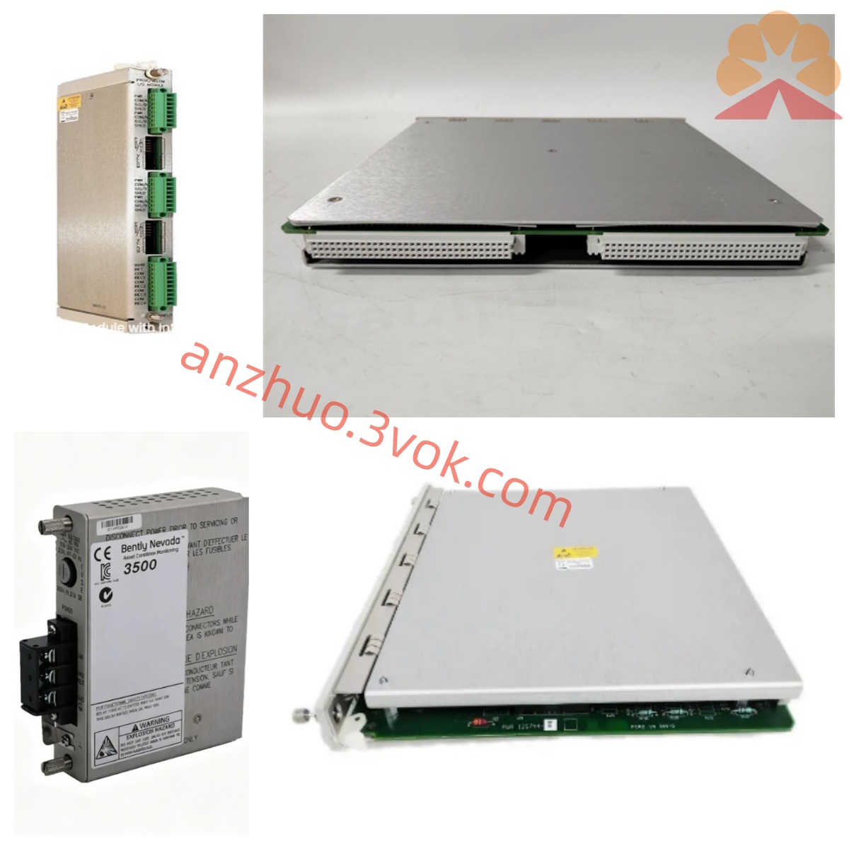
Bently Nevada 133827-02 (3500/61 Non-Isolated RTD/TC Input I/O Module) Product Specification
133827-02 is the rear external termination I/O board matching Bently Nevada 3500/61 front temperature monitoring module, belonging to core temperature signal acquisition accessory of the 3500 series turbomachinery protection and condition monitoring system manufactured in USA. Designed for non-isolated field wiring connection, it pairs with front-panel 3500/61 main card to build complete multi-channel temperature measurement unit dedicated to RTD resistance temperature detector and TC thermocouple signal collection for critical rotating equipment including steam turbines, centrifugal compressors and blowers in thermal power, petrochemical and metallurgical industries. This rear I/O card is mounted at the backside of standard 3500/05 instrument rack backplane, adopting conformal coated circuit board to resist cabinet oil mist, dampness and corrosive industrial gas erosion; it is the revised version upgraded from former 133827-01 edition with optimized terminal circuit anti-interference and wiring protection design.
Description
Bently Nevada 133827-02 (3500/61 Non-Isolated RTD/TC Input I/O Module) Product Specification
1. Product Overview
133827-02 is the rear external termination I/O board matching Bently Nevada 3500/61 front temperature monitoring module, belonging to core temperature signal acquisition accessory of the 3500 series turbomachinery protection and condition monitoring system manufactured in USA. Designed for non-isolated field wiring connection, it pairs with front-panel 3500/61 main card to build complete multi-channel temperature measurement unit dedicated to RTD resistance temperature detector and TC thermocouple signal collection for critical rotating equipment including steam turbines, centrifugal compressors and blowers in thermal power, petrochemical and metallurgical industries. This rear I/O card is mounted at the backside of standard 3500/05 instrument rack backplane, adopting conformal coated circuit board to resist cabinet oil mist, dampness and corrosive industrial gas erosion; it is the revised version upgraded from former 133827-01 edition with optimized terminal circuit anti-interference and wiring protection design.
2. Core Functional Description
2.1 Multi-Type Temperature Signal Terminal Distribution
The module serves as external wiring transit carrier for six independent temperature input channels of matched 3500/61 front board, supporting direct non-isolated access of mainstream industrial RTD and thermocouple signals without intermediate isolation barrier accessory. Compatible RTD types include Pt100, Cu50 standard platinum and copper thermal resistance sensors, while thermocouple input covers K, E, J, T, S, B common thermocouple specifications widely applied for bearing bush, cylinder casing and pipeline surface temperature measurement of large rotating machinery. All field sensor cables are fixed on onboard external terminal connectors to realize centralized wiring layout of rack rear side, simplifying on-site wiring construction and later maintenance inspection work.
2.2 Raw Signal Transmission & Pre-filter Processing
After receiving analog temperature signals from field RTD and TC sensors via external wiring terminals, 133827-02 conducts primary passive EMI filtering inside onboard circuit to restrain high-frequency electromagnetic interference introduced from surrounding power cables and frequency conversion equipment, then transmits conditioned analog signals to front 3500/61 measurement main card through rack internal backplane dedicated bus for high-precision AD conversion and temperature value calculation. It synchronously feeds back module terminal wiring state and channel open/short-circuit fault signal to front panel indicator and system configuration software, enabling real-time wiring abnormality monitoring for maintenance staff.
2.3 Configuration Data Backing & Channel Status Upload
All channel parameter configurations including sensor type selection, temperature range definition, alarm threshold setting and sensor sensitivity calibration data set by official 3500 configuration software are synchronized stored into nonvolatile memory chip equipped on 133827-02, preventing configuration parameter loss caused by instantaneous rack power failure or short-time power cut. The module continuously uploads real-time measured temperature value, pre-alarm/trip trigger status and each channel fault code through backplane bus to rack gateway module, further forwarding data to System 1 online monitoring platform and plant DCS/PLC control system for centralized equipment running state management.
2.4 Built-in Terminal Circuit Self-diagnosis
Embedded circuit monitoring circuit regularly detects terminal wiring open circuit, short circuit, overvoltage input and onboard auxiliary power supply abnormal condition of all six input channels. Once abnormal wiring or hardware fault is detected, corresponding fault codes are recorded in local storage and uploaded to upper monitoring system synchronously, helping field maintenance personnel rapidly locate faulty channel and damaged wiring position without dismantling whole rack equipment.
3. Mechanical Dimension & Structure Specification
133827-02 follows unified single-width rear I/O card mechanical dimension standard of Bently 3500 series rack, matching outline size of front-mounted 3500/61 main module; gold-plated edge connector is adopted on circuit board edge for tight plug-in connection with 3500/05 rack backplane slot to guarantee stable power supply and bus signal transmission under long-term cabinet mechanical vibration environment from adjacent operating equipment. The module is fixed via dedicated locking buckle matching rack rear installation structure, overall net weight is approximately 0.40 kilogram, all internal electronic components adopt industrial anti-vibration layout design to adapt harsh on-site cabinet installation environment. External wiring terminals adopt pluggable terminal block structure allowing quick cable disassembly and replacement during equipment overhaul without affecting other normal operating monitoring channels.
4. Electrical Technical Parameters
All working power of this rear I/O module is directly supplied by 3500 rack backplane with rated input DC voltage 24VDC ±10%, typical average power consumption under full-load six-channel normal operating condition is less than 2.8W. Each independent input channel is equipped with ESD electrostatic protection and transient surge suppression components to block instantaneous overvoltage damage generated by field miswiring and lightning induction. Signal transmission between terminal circuit and front measurement card follows 3500 dedicated internal bus specification with stable low noise analog signal transmission performance to ensure overall temperature measuring precision of the complete 3500/61 unit. The module belongs to non-isolated wiring design, all field sensor loops share common reference ground with rack internal circuit, requiring strict equipotential grounding construction at industrial installation site to avoid ground loop interference affecting measuring accuracy.
5. Environmental Working Conditions
Rated continuous operating ambient temperature range is -30℃ ~ +65℃, short-time intermittent peak working temperature up to +70℃ will not lead to permanent damage of internal electronic elements; spare part storage temperature range covers -40℃ ~ +85℃, requiring sealed dry storage environment far away from acid-base corrosive gas and violent mechanical collision impact. Applicable working relative humidity scope is 5%RH ~ 95RH under non-condensing environment, suitable for high dust, high humidity and slight oil mist control cabinet environment of thermal power, petrochemical, coal chemical and offshore oil and gas industries, complying with API670 international machinery protection standard and CE industrial EMC anti-interference certification specification.
6. Version Matching & Replacement Regulation
133827-02 is updated revision of original 133827-01 rear I/O board with improved terminal protection circuit and signal filtering performance; these two versions cannot be randomly cross-replaced during field maintenance without official factory configuration confirmation, mismatched front and rear module combination will result in channel measuring failure or abnormal temperature data fluctuation. This rear board must be exclusively paired with corresponding version 3500/61 front temperature measurement module, mismatched front and rear assembly leads to communication interruption between backplane bus and measurement channel. The product is standard non-intrinsically safe type, cannot be directly installed inside explosion hazardous area cabinet without matched safety barrier isolation accessories for field sensor wiring.
7. Main Industrial Application Scope
Matched with 3500/61 front main card to form full-function six-channel temperature monitoring unit, 133827-02 is widely installed in critical equipment TSI protection cabinets across global energy and heavy process industry. Core application scenarios include steam turbine generator set bearing temperature monitoring cabinet of thermal power plants, large hydrogen compressor and feed gas compressor casing temperature measurement system of petrochemical plants, high-speed induced draft fan and blast furnace blower bearing bush monitoring cabinet of metallurgy production lines, as well as onshore and offshore oil-gas platform turbomachinery safety protection system, realizing long-term continuous temperature tracking and over-temperature protection interlock function for key rotating equipment components.
8. Factory Test and After-sales Warranty Terms
Every brand-new original 133827-02 undergoes comprehensive pre-delivery factory inspection including full six-channel wiring continuity test, continuous powered aging burn-in test, high-low temperature cyclic reliability screening and full-range RTD/TC signal input calibration to verify all electrical and mechanical indicators comply with original US factory design specification. Manufacturer standard warranty period is twelve months starting from formal product delivery date; free hardware repair or replacement service is available for inherent manufacturing defects emerging within valid warranty period and rated working environment. Module damage induced by unauthorized disassembly, wrong field wiring, external lightning surge overvoltage impact, artificial mechanical collision and corrosive medium erosion is excluded from free warranty coverage range.
Get a Quote