Bently Nevada 136719-01 Grounding I/O Rear Terminal Module Full Product Specification
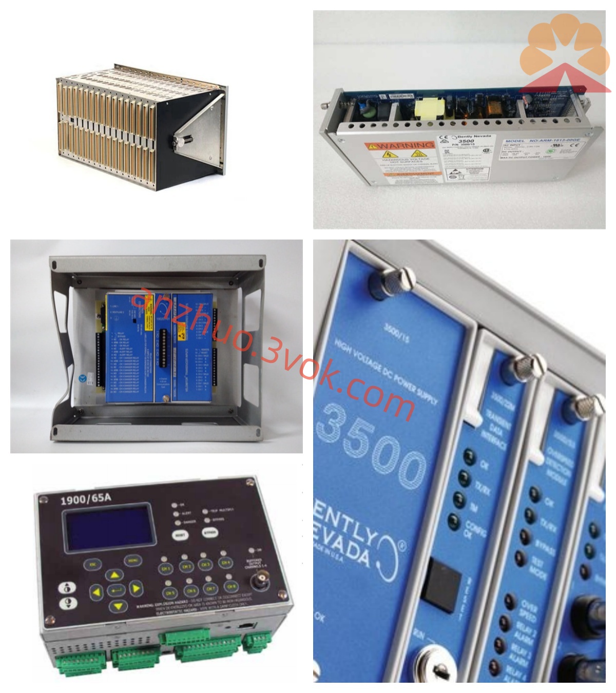
136719-01 is the original factory rear I/O grounding terminal accessory exclusively matched with Bently Nevada 3500/04 monitor front card under Baker Hughes 3500 TSI machinery protection product line, manufactured in the United States as a dedicated backplane wiring board for system earthing and sensor signal wiring management. This rear module is installed on the rear slot of standard 3500 rack chassis and electrically interconnected with front 3500/04 main monitor card via internal rack backplane connector, serving as the core intermediate wiring carrier for field sensor cable access, unified system grounding distribution and signal loop noise suppression of the monitoring channel. It follows the unified single-width mechanical specification of 3500 series rear I/O modules and supports hot-swap maintenance without shutting down the entire rack power supply during on-site replacement and overhaul. The module is mainly designed to solve ground potential drift and electromagnetic interference problems of multi-channel measuring circuits, standardizing the earthing path of all field connected proximity probes, seismic accelerometers and auxiliary transducer cables, and is widely stocked as spare part for retrofit and maintenance of legacy turbine, compressor monitoring systems in thermal power, petrochemical and gas industry projects.
Description
Bently Nevada 136719-01 Grounding I/O Rear Terminal Module Full Product Specification
1. General Overview
136719-01 is the original factory rear I/O grounding terminal accessory exclusively matched with Bently Nevada 3500/04 monitor front card under Baker Hughes 3500 TSI machinery protection product line, manufactured in the United States as a dedicated backplane wiring board for system earthing and sensor signal wiring management. This rear module is installed on the rear slot of standard 3500 rack chassis and electrically interconnected with front 3500/04 main monitor card via internal rack backplane connector, serving as the core intermediate wiring carrier for field sensor cable access, unified system grounding distribution and signal loop noise suppression of the monitoring channel. It follows the unified single-width mechanical specification of 3500 series rear I/O modules and supports hot-swap maintenance without shutting down the entire rack power supply during on-site replacement and overhaul. The module is mainly designed to solve ground potential drift and electromagnetic interference problems of multi-channel measuring circuits, standardizing the earthing path of all field connected proximity probes, seismic accelerometers and auxiliary transducer cables, and is widely stocked as spare part for retrofit and maintenance of legacy turbine, compressor monitoring systems in thermal power, petrochemical and gas industry projects.
2. Core Functional Description & Wiring Layout
The core design objective of 136719-01 focuses on centralized system grounding management and multi-channel signal terminal distribution for matched 3500/04 monitor card, integrating independent signal wiring terminals and dedicated safety grounding bus terminals on onboard screw-type terminal blocks. It reserves four groups of independent signal channel terminals corresponding to four measuring channels of front 3500/04 monitor, separately receiving wiring from eddy current displacement probes, seismic vibration sensors and Keyphasor speed pickups deployed on site rotating equipment. All channel signal loops converge to the module’s built-in common grounding busbar to realize equipotential grounding for the whole measuring system, effectively eliminating circulating ground current and low-frequency interference induced by different ground potential of field equipment cabinet and equipment base, which greatly improves the measuring accuracy of weak sensor signals. Besides regular measuring signal terminals, the module is equipped with intrinsic safety isolation grounding terminals for hazardous area wiring configuration, which can match explosion-proof transducer circuits of Class I Division 2 dangerous working conditions to cut off surge voltage transmission between hazardous side and safe side of the control cabinet. It also routes all channel fault detection signals and configured alert/danger alarm dry contact signals from front monitor card to reserved auxiliary terminals for external relay interlock and local alarm annunciator wiring requirements.
3. Electrical Performance & Circuit Protection Parameters
The module acquires all operating auxiliary power from 3500 rack internal DC backplane bus without independent external power input, with total power consumption controlled below 3.2W under full-load wiring condition of all four measuring channels connected with field sensors. The internal printed circuit board is coated with three-proof conformal insulating paint against moisture, oil mist and corrosive gas erosion inside turbine room and refinery central control cabinet to maintain long-term stable circuit performance under high-humidity industrial environment. Every signal input terminal is embedded with built-in transient surge suppression circuit and short-circuit protection component, which can absorb instantaneous overvoltage caused by lightning induction, field cable misconnection and short-circuit fault, avoiding damage to front 3500/04 monitor core circuit from external electrical impact. The common grounding bus on the module adopts thickened copper alloy conductive structure with low DC resistance, ensuring stable equipotential connection for all channel grounding points; the whole signal transmission error brought by grounding potential fluctuation is controlled within ±0.5% full scale to meet high-precision online monitoring standard of critical rotating machinery protection system. Rated applicable input signal voltage range for field transducer wiring covers 0V~10VDC, adapting to standard output signal specification of mainstream Bently proximity and seismic sensors.
4. Mechanical Dimension & Structural Design Standard
Compliant with universal single-width rear module dimensional standard of full series 3500 rack accessories, overall outer dimension is 177.8mm in height, 48.3mm in width and 254mm in installation depth, with net product weight approximately 0.40kg. The module outer shell is made of die-cast aluminum alloy shielding housing to isolate electromagnetic radiation interference from surrounding high-current power cables and frequency conversion equipment inside cabinet, optimizing anti-interference capability of weak analog measuring signals. Multiple rows of pluggable green screw terminal blocks are arranged on the outer side of the module for convenient on-site wire fixation and disassembly without extra intermediate terminal box configuration, simplifying cabinet secondary wiring layout and reducing construction cost. Locking buckle structure is set on module side edge for firm fixation inside rack rear mounting slot to prevent poor backplane contact caused by mechanical vibration of nearby large rotating equipment and cabinet shaking during long-term operation, compatible with all standard 7-slot compact and 14-slot full-size 3500/05 rack chassis models seamlessly. Partial specification variant of this module supports DIN rail independent installation for decentralized cabinet wiring scenarios besides standard rack rear plug-in installation.
5. Environmental Operating & Storage Specification
Rated continuous long-term operating ambient temperature ranges from -40°C to +82°C, and can withstand intermittent short-time peak working temperature up to +85°C without irreversible parameter drift of internal electronic components and conductive structure deformation. Applicable working relative humidity scope is 5%RH~95%RH under non-condensing environment, adapting to severe working environment with dense dust, oil vapor and high humidity of thermal power plant turbine island, petrochemical refining workshop and natural gas compression station central control room. Specified product storage temperature range spans from -45°C to +90°C; storage environment requires dry closed warehouse placement away from acid-base corrosive gas, liquid immersion and violent mechanical collision damage to avoid terminal oxidation and internal circuit failure. Original factory finished product has passed CE industrial EMC electromagnetic compatibility certification and anti-vibration durability test; intrinsically safety customized version for explosive hazardous area is available upon special customer order for cabinet installation in flammable gas concentration production workshop.
6. System Matching & Industrial Application Scope
136719-01 must be used in paired combination with 3500/04 front monitor card and installed on corresponding rear slot of 3500 rack, cooperating with rack power supply module, 3500/22M TDI communication module, relay output modules and other front monitoring cards to construct complete set of unit TSI machinery safety protection system. After finishing field sensor wiring via this grounding I/O module, the measured vibration, displacement and speed data collected by front monitor card is converted into standard 4–20mA analog signal and transmitted through module corresponding output terminals to plant central DCS system for real-time parameter display and centralized alarm management; meanwhile digital trend and fault waveform data is uploaded via rack communication bus to System 1 predictive maintenance platform for historical curve storage and mechanical fault diagnosis analysis. Core application fields cover steam turbine generator set monitoring in thermal power industry, large centrifugal compressor and hydrogen compressor protection in petrochemical industry, heavy-duty fan and feed pump condition supervision in metallurgy industry as well as offshore oil and gas production equipment online monitoring projects across global energy sectors.
7. Factory Inspection & Official Warranty Terms
Each brand-new original 136719-01 undergoes comprehensive outgoing factory inspection before delivery, including full-channel wiring continuity test, grounding impedance calibration, high-low temperature cycle aging screening and surge withstand test to verify all electrical and mechanical indicators comply with US original factory design specification and API670 industrial machinery protection standard. Original manufacturer standard warranty period is twelve months counted from formal product delivery date; free repair or replacement service is provided for hardware failure induced by inherent manufacturing defects under rated specified installation and operating environment within valid warranty term. Damage resulting from unauthorized module housing disassembly, wrong field wiring configuration, external lightning overvoltage surge, artificial mechanical impact and chemical corrosion is excluded from free warranty coverage range.
Get a Quote