Bently Nevada 140072-04 (3500/45 Four-Channel Position Monitor Module) Full Product Specification
140072-04 is the official factory part number of Bently Nevada 3500/45 four-channel configurable position monitoring module, a core functional component belonging to the globally recognized 3500 series TSI machinery protection system manufactured by Bently Nevada (a GE-owned brand originated from the United States). Designed exclusively for continuous position parameter measurement and safety interlock protection of critical rotating machinery, this monitor serves as a standard configuration for steam turbine, large centrifugal compressor and heavy pump sets deployed across thermal power, petrochemical, natural gas compression and metallurgical industries. Different from vibration-only monitoring modules like 3500/40M and 3500/42M, the 3500/45 with part code 140072-04 focuses on all kinds of linear and angular displacement measurement, supporting five mainstream types of industrial position transducers for flexible field configuration. The module adopts single-width standard rack structure matching the full range of 3500 rack chassis, supporting hot-swap online replacement under live powered rack condition without shutting down the whole monitoring system, effectively shortening equipment maintenance downtime and avoiding unexpected unit outage risk. It cannot operate independently and must be plugged into standard 3500 rack equipped with backplane power supply and rack interface communication card to complete data interaction and power supply via rack internal backplane bus.
Description
Bently Nevada 140072-04 (3500/45 Four-Channel Position Monitor Module) Full Product Specification
1. General Product Overview
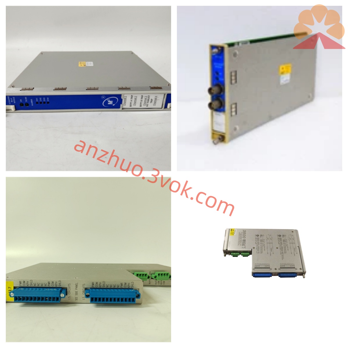
140072-04 is the official factory part number of Bently Nevada 3500/45 four-channel configurable position monitoring module, a core functional component belonging to the globally recognized 3500 series TSI machinery protection system manufactured by Bently Nevada (a GE-owned brand originated from the United States). Designed exclusively for continuous position parameter measurement and safety interlock protection of critical rotating machinery, this monitor serves as a standard configuration for steam turbine, large centrifugal compressor and heavy pump sets deployed across thermal power, petrochemical, natural gas compression and metallurgical industries. Different from vibration-only monitoring modules like 3500/40M and 3500/42M, the 3500/45 with part code 140072-04 focuses on all kinds of linear and angular displacement measurement, supporting five mainstream types of industrial position transducers for flexible field configuration. The module adopts single-width standard rack structure matching the full range of 3500 rack chassis, supporting hot-swap online replacement under live powered rack condition without shutting down the whole monitoring system, effectively shortening equipment maintenance downtime and avoiding unexpected unit outage risk. It cannot operate independently and must be plugged into standard 3500 rack equipped with backplane power supply and rack interface communication card to complete data interaction and power supply via rack internal backplane bus.
2. Supported Transducer Input Types & Core Monitoring Functions
This four-channel monitor features paired channel grouping design: Channel 1 and Channel 2 form one functional group, while Channel 3 and Channel 4 compose another independent group; each group can be programmed for one fixed measurement function via official 3500 system configuration software, meaning one single 140072-04 module can realize maximum two different position monitoring tasks simultaneously. The module accepts input signals from five categories of industry-standard sensors: non-contact eddy-current proximity probes, AC-type LVDT, DC-type LVDT, Rotary Position Transducers (RPT), and rotary potentiometers, covering all mainstream position detection solutions for large rotating equipment. Its configurable monitoring functions mainly include axial thrust displacement measurement for rotor axial float and thrust bearing abrasion supervision, multiple modes of turbine differential expansion including single-slope, dual-slope and compensation-type differential expansion for rotor-casing thermal expansion gap monitoring, casing absolute expansion measurement only available on Channel 3 and Channel 4 group, as well as valve stem stroke and actuator position tracking with LVDT and potentiometer inputs. After receiving raw signals from field sensors, the onboard signal conditioning circuit finishes impedance matching, noise filtering and signal demodulation, then the built-in microprocessor converts analog signals into accurate digital measured values for subsequent threshold comparison and data transmission.
3. Alarm Logic & Signal Output Specifications
Users can program two-stage threshold parameters including Alert early warning setpoint and Danger shutdown trip setpoint for every single channel through upper computer configuration software according to actual equipment operating requirements. When real-time measured position value exceeds pre-defined Alert limit, the module marks corresponding channel abnormal status and sends warning instruction via backplane bus to drive external relay modules for local alarm notification; once measurement breaks Danger threshold, it triggers hard-wire shutdown interlock signal to stop protected machinery and prevent severe mechanical damage caused by excessive displacement failure. The module reserves multiple standard output interfaces for field data transmission: proportional isolated 4–20mA analog recorder output compatible with mainstream DCS distributed control system, short-circuit protected buffered transducer output via front-panel coaxial connectors for oscilloscope waveform verification and secondary signal collection on site. All alarm event logs, threshold modification records and abnormal transient data are stored in non-volatile onboard memory to avoid data loss during instantaneous power fluctuation or unexpected power cut of control cabinet. Three status LED indicators mounted on module front panel: OK lamp reflects normal power and internal circuit running status, TX/RX lamp displays backplane data communication working condition, and Bypass lamp lights up when related channel is manually locked to suspend alarm output temporarily for maintenance work.
4. Electrical Parameter & Power Consumption
The module obtains all operating power directly from 3500 rack backplane DC power bus without any external auxiliary power source; rated total power consumption under full four-channel loaded working status is controlled around 7W, with minor fluctuation based on different configured sensor types. Built-in multi-level ESD protection, surge suppression and short-circuit prevention circuit on each input terminal to defend front-end electronic components from damage induced by field wiring mistake, cable short connection or instantaneous industrial overvoltage surge in complex electromagnetic environment beside high-power frequency converters and large driving motors. The full-scale measurement precision of the monitor is controlled within ±1% full scale under calibrated standard ambient condition, meeting high-precision position monitoring requirement for critical power and petrochemical units. Input terminal circuit is designed with standard input impedance matching parameters to match the output electrical characteristics of compatible proximity probes and LVDT transducers, eliminating signal attenuation and measurement distortion caused by impedance mismatch of field connecting cables.
5. Mechanical Dimension & Structural Design
Following unified single-width dimension standard of all 3500 series plug-in monitoring modules, the overall outer dimension is 177.8mm in height, 48.3mm in width and 254mm in installation depth, with net product weight approximately 0.4kg. Front panel is manufactured with die-cast aluminum alloy shielding shell processed by conductive anti-oxidation coating to isolate external electromagnetic interference from surrounding high-voltage equipment and power cables inside control cabinet. The whole internal printed circuit board is coated with three-proof conformal paint to resist erosion from cabinet condensed moisture, oil mist and corrosive volatile chemical vapor existing in turbine house and refinery central control room environment, improving long-term service stability under harsh industrial working conditions. Different from integrated-termination monitor modules, 140072-04 needs matched external separate termination board for all field sensor wiring and analog output cable connection, all field wires are terminated on independent rear terminal accessory instead of module body, facilitating centralized cabinet wiring arrangement and later circuit maintenance troubleshooting. Standard mechanical locking structure on module edge ensures stable plug-in fixation inside rack slot against vibration loose caused by equipment mechanical vibration transmitted from adjacent rotating machines.
6. Environmental Operating & Storage Specifications
Continuous rated operating ambient temperature range for long-term stable monitoring is from -40°C up to +70°C; short-time intermittent peak ambient temperature can withstand maximum +85°C without permanent component parameter drift or hardware performance degradation. Applicable working relative humidity covers 5%RH to 95%RH under non-condensing environment condition, adapting to high-humidity, high-dust and oil-fog concentrated workshop environment of gas compression stations and chemical refining plants. Product storage ambient temperature range spans from -45°C to +90°C, requiring dry sealed warehouse storage away from acid-base volatile gas, corrosive liquid immersion and severe mechanical collision damage. Original factory version has passed CE EMC certification and industrial anti-vibration durability testing; customized intrinsically safe model certified for Class I Division 2 hazardous explosive area is available upon customer special order for installation inside flammable gas concentrated process plant control cabinets.
7. System Matching & Industrial Application Fields
Multiple 140072-04 modules can be installed into different vacant slots of one standard 3500 rack together with vibration monitor modules, speed monitor cards, relay output modules and rack power supply units to build an integrated complete TSI protection system for whole turbine-compressor train set centralized monitoring. Processed real-time position data is transmitted via rack interface module Ethernet port to two upper-layer industrial platforms: System 1 predictive maintenance diagnostic system for historical trend tracking, fault spectrum analysis and early failure diagnosis of rotor thermal expansion abnormality and thrust bearing wear; plant central DCS control system via isolated 4–20mA analog signals for real-time position value display and unified interlock alarm management in control room. Main application scenarios include steam turbine unit TSI safety monitoring for thermal power generation plants, centrifugal compressor rotor axial displacement and casing expansion supervision for petrochemical refining production lines, natural gas field compressor set valve position and differential expansion online monitoring, as well as large industrial feed water pump and fan group mechanical protection in metallurgy and mining industry.
8. Factory Inspection & Warranty Terms
Every brand-new original 140072-04 module undergoes strict full-range factory quality inspection before shipment, including continuous power aging burn-in test, four-channel full function calibration with standard Bently proximity probes and LVDT sensors, high-low temperature cyclic reliability screening and all input-output circuit continuity testing to ensure all electrical and mechanical indicators comply with original US factory design specifications. Original manufacturer’s standard warranty period is twelve months calculated from formal product delivery date; free repair or replacement service is provided for hardware damage induced by inherent manufacturing defects under rated installation and specified operating environment within valid warranty term. Damage caused by unauthorized module housing disassembly, incorrect field wiring, external overvoltage impact, artificial mechanical collision and chemical corrosion is excluded from free warranty coverage scope.
Get a Quote