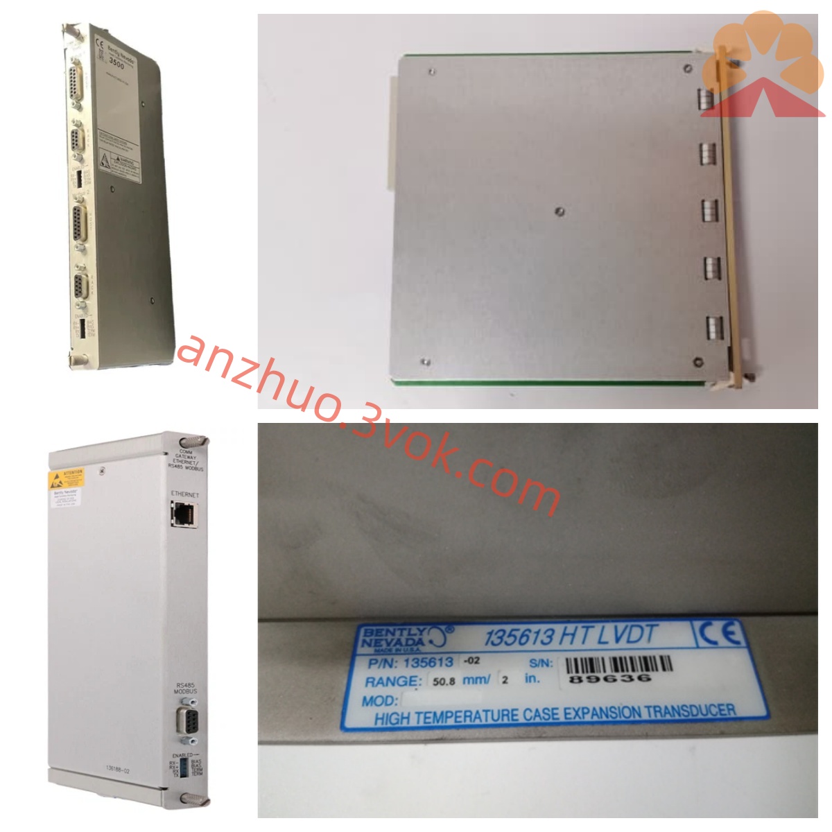
Bently Nevada 149992-01 Rear I/O Terminal Board for 3500/33 Relay Output Module Product Specification
149992-01 is the factory original rear wiring terminal board designed to mate with front control board 149986-01, forming a complete set of Bently Nevada 3500/33 sixteen-channel relay output module within the 3500 rack-based TSI machinery protection system. As the external signal outgoing component of the relay module, this rear board serves as the physical wiring interface to lead out all sixteen independent relay dry contact terminals from the front control circuit to field external control circuits. It receives logic drive commands transmitted from the front card via internal interconnection, and converts Alert pre-alarm and Danger trip signals generated by vibration, temperature and speed monitor modules inside the 3500 rack into on-site hard-wired switching signals for audible-visual alarms, equipment shutdown solenoid valves and DCS interlock loops. Widely applied across thermal power, petrochemical refining and metallurgical industries for steam turbine-generator sets, large centrifugal compressors and heavy-duty auxiliary pump unit safety protection, the whole assembly is compliant with API 670 machinery protection standards.
Description
Bently Nevada 149992-01 Rear I/O Terminal Board for 3500/33 Relay Output Module Product Specification
1. Product Overview
149992-01 is the factory original rear wiring terminal board designed to mate with front control board 149986-01, forming a complete set of Bently Nevada 3500/33 sixteen-channel relay output module within the 3500 rack-based TSI machinery protection system. As the external signal outgoing component of the relay module, this rear board serves as the physical wiring interface to lead out all sixteen independent relay dry contact terminals from the front control circuit to field external control circuits. It receives logic drive commands transmitted from the front card via internal interconnection, and converts Alert pre-alarm and Danger trip signals generated by vibration, temperature and speed monitor modules inside the 3500 rack into on-site hard-wired switching signals for audible-visual alarms, equipment shutdown solenoid valves and DCS interlock loops. Widely applied across thermal power, petrochemical refining and metallurgical industries for steam turbine-generator sets, large centrifugal compressors and heavy-duty auxiliary pump unit safety protection, the whole assembly is compliant with API 670 machinery protection standards.
2. Working Principle and Internal Structure
Adopting split front-and-rear card structure exclusive for 3500 series rack layout, the front board 149986-01 is plugged into standard 3500 rack slot to receive digital alarm data from rack backplane bus and complete internal relay logic computation, while 149992-01 is installed at the rear corresponding position of the same slot to realize external wiring expansion. Internal wiring traces on the terminal board connect directly with relay contact pins coming from the front card via dedicated gold-plated interconnection connectors, without additional intermediate signal conversion circuits. Each relay channel is routed to independent pluggable European-style terminal blocks mounted on the edge of the rear board, facilitating convenient field cable termination and later maintenance disconnection. The entire PCB is coated with protective conformal coating to resist moisture, dust and mild corrosive gas erosion inside industrial control cabinets and improve long-term running stability under oil mist environment.
3. Electrical Performance Specifications
All sixteen channels provide Form C passive dry contact output without built-in internal power source on the terminal board itself; all contact power supply is provided externally by field user control loops. Each relay contact bears standard rated switching capacity for industrial control circuits, supporting connection of AC and DC interlock circuits commonly used for equipment protection and alarm loops. The terminal board draws no separate rack operating power, obtaining all signal correlation from mechanical interconnection with the paired front control card, with no additional power consumption on its own circuit. Built-in terminal short-circuit isolation layout prevents cross-channel short-circuit failure caused by on-site wiring misoperation; the board’s internal wiring is strictly separated per channel to eliminate mutual signal interference between different protection loops.
4. Mechanical and Mounting Features
149992-01 follows unified rear I/O dimensional specification of Bently 3500 series rack rear wiring accessories, fixed at the back side of the rack aligned with the corresponding front 3500/33 card slot. Equipped with industry-standard detachable screw-type European terminal blocks for every outgoing channel, users can fasten field shielded control cables easily without specialized crimp tools. The overall board is assembled inside a flame-retardant plastic outer frame with positioning buckle design to avoid loose displacement induced by long-term continuous mechanical vibration from nearby running rotating machinery. Compact structural layout optimizes cabinet internal wiring space arrangement and facilitates single terminal overhaul without disassembling the whole module from rack.
5. Environmental Operating Parameters
Permitted continuous working ambient temperature ranges from -30℃ to +70℃; short-term intermittent peak working temperature can reach +75℃ to adapt high-temperature cabinet surroundings adjacent to steam pipelines and hot process equipment. Rated applicable working relative humidity is 5%RH to 95%RH under non-condensing condition, maintaining stable wiring performance in dusty and oil-fog filled industrial workshop environment. Spare part storage temperature spans -40℃ to +85℃ under dry indoor warehouse storage conditions. The finished product passes CE EMC certification and anti-vibration testing to withstand continuous ambient vibration impact generated by surrounding industrial rotating equipment.
6. System Matching and Application Guidance
This rear terminal board must be matched exclusively with original front card 149986-01 to constitute complete functional 3500/33 relay module and cannot work independently without paired front control hardware. The complete relay set cooperates with all standard 3500 series monitor modules including proximity vibration cards, seismic monitor cards, temperature acquisition modules and Keyphasor speed boards to build full-set equipment interlock protection logic. After finishing field wiring on 149992-01 terminals, users configure alarm threshold and relay voting logic via official 3500 configuration software on upper computer. When monitored parameters exceed preset Alert or Danger limits, corresponding relay contacts on the rear board switch status to trigger on-site audible alarm or emergency equipment shutdown interlock. Typical application covers steam turbine protection trip circuits in power plants, compressor safety interlock loops in petrochemical plants and large blower over-vibration alarm circuits in metallurgical production lines.
7. Factory Inspection and Warranty Terms
Every finished 149992-01 unit undergoes continuity test of all terminal channels, wiring integrity inspection and high-low temperature cycling test before factory delivery to verify reliable connection performance of each outgoing path. Standard original manufacturer warranty period is twelve months starting from product delivery date. Within valid warranty coverage, free repair or replacement is available for failures resulting from original manufacturing defects under specified standard installation and normal working environment. Damages caused by improper wiring, overvoltage input, artificial physical damage and chemical corrosion are excluded from free warranty service scope.
Get a Quote