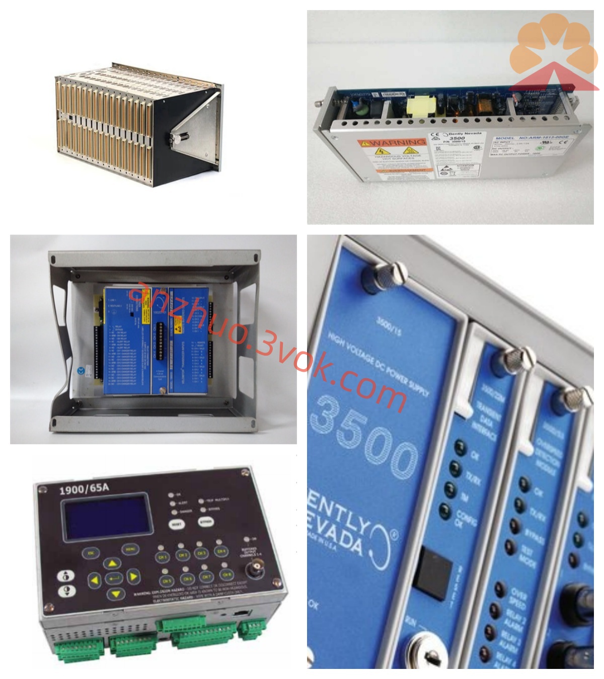
Bently Nevada 170180-01-00 FieldMonitor External Transducer I/O Module Product Specification
170180-01-00 is the standard part number of Bently Nevada FieldMonitor series external transducer I/O interface module, manufactured in the United States and belonging to the 1701 FieldMonitor decentralized machinery condition monitoring product line, designed to serve as an on-site signal intermediate interface between field-mounted proximity probes, accelerometers, tachometer transducers and upper monitoring rack or distributed control system. Different from the rack-plug-in 3500 series monitoring cards, this unit adopts independent DIN rail or panel fixed installation instead of slot-type rack installation, realizing decentralized signal collection near turbomachinery bearing housings, pump casings and compressor equipment, effectively shortening field sensor wiring length and reducing external electromagnetic interference impact on weak vibration signals.
Description
Bently Nevada 170180-01-00 FieldMonitor External Transducer I/O Module Product Specification
1. Product Overview
170180-01-00 is the standard part number of Bently Nevada FieldMonitor series external transducer I/O interface module, manufactured in the United States and belonging to the 1701 FieldMonitor decentralized machinery condition monitoring product line, designed to serve as an on-site signal intermediate interface between field-mounted proximity probes, accelerometers, tachometer transducers and upper monitoring rack or distributed control system. Different from the rack-plug-in 3500 series monitoring cards, this unit adopts independent DIN rail or panel fixed installation instead of slot-type rack installation, realizing decentralized signal collection near turbomachinery bearing housings, pump casings and compressor equipment, effectively shortening field sensor wiring length and reducing external electromagnetic interference impact on weak vibration signals.
This module supports access of two mainstream sensor types including eddy current proximitor and piezoelectric accelerometer, providing regulated working power supply for connected transducers while completing original signal conditioning, filtering and preliminary signal conversion, then transmitting processed digital or analog measurement data via standard industrial bus to host monitoring equipment or DCS control platform. It is widely matched with steam turbine, centrifugal compressor, large industrial blower and feed pump monitoring systems across thermal power, petrochemical, metallurgy and refining industries to implement continuous online monitoring of shaft radial vibration, axial thrust displacement and casing absolute vibration parameters. The complete product has obtained ATEX, CSA and Class1 Division2 hazardous area certification to satisfy installation requirements for explosive hazardous industrial working environments.
2. Core Functional Description
2.1 Dual-channel Multi-type Transducer Access Function
The module reserves two independent isolated measurement channels labeled Channel A and Channel B respectively, each channel can be flexibly configured via upper configuration software to connect either -24VDC powered eddy current proximitor system or loop-type piezoelectric accelerometer without hardware modification. When set for proximitor input, it receives displacement analog signal from 3300XL and 21000 series proximity transducer, completes gap static value and alternating vibration amplitude calculation based on factory-calibrated transducer sensitivity of 7.87V/mm; under accelerometer working mode, it supplies constant current excitation power for vibration speed/acceleration sensors and converts high-frequency vibration acceleration signal into standard displacement or velocity output after integral operation. Two channels operate independently without signal cross-interference, enabling simultaneous collection of two different measuring parameter signals on a single module.
2.2 On-board Signal Conditioning and Alarm Processing
Built-in multi-stage active filter circuit inside the module, users can customize cutoff frequency through configuration software to filter out high-frequency mechanical clutter and low-frequency power frequency interference according to actual equipment rotating speed characteristics. Each channel supports two-level configurable Alert pre-alarm and Danger dangerous threshold, once measured parameter exceeds preset setpoint, the module triggers local status indication and transmits alarm information together with real-time measured value to upper system via communication bus; meanwhile, optional passive dry contact switching signal can be output for local on-site light alarm or auxiliary interlock control loop connection. All alarm delay time, bypass function and threshold parameters support online remote modification without stopping module operation.
2.3 Dual-form Data Output Mechanism
The module equips two kinds of data output modes for system access demands: analog quantity output and digital bus communication output. Every measuring channel provides isolated 4–20mA linear analog output corresponding to full measuring range of configured parameter, directly connecting to DCS/PLC analog input card for centralized process data collection and historical trending recording. Digital communication interface adopts standard RS485 physical layer with Modbus RTU industrial protocol, supporting multi-module bus networking connection, multiple 170180 series modules can be cascaded on one communication bus to upload all measurement data, channel fault status and module self-check information to upper computer monitoring platform synchronously. Partial derivative versions of this model reserve DeviceNet communication interface option for access of mainstream fieldbus control system.
2.4 Comprehensive Built-in Self-diagnosis System
Continuous cyclic self-detection runs automatically after module power-on, covering internal power circuit, channel input loop, sensor open/short-circuit state and bus communication link status. Front panel configures multiple status indicator lamps: power running lamp stays solid green under normal working condition; channel fault lamp turns yellow when connected transducer appears open circuit, short circuit or power abnormal fault; communication lamp flickers periodically during normal data interaction with upper host. Once any channel fault is detected, corresponding fault code is marked and uploaded via communication bus to facilitate maintenance staff rapid fault location and troubleshooting; meanwhile faulty channel can be manually set to bypass state to suspend alarm judgment during on-site sensor replacement and equipment overhaul.
3. Electrical Performance Specifications
Rated operating power supply of the module is 24VDC direct current, acceptable input voltage fluctuation range covers 18VDC to 36VDC, total typical power consumption of full-load dual-channel working status is controlled below 4 watts, supporting wide-range unstable field power supply environment. For proximitor input channel, matched standard transducer input impedance is 10kΩ, compatible with all original Bently Nevada series proximity probes and matched extension cables; accelerometer channel provides constant current excitation of 4mA for piezoelectric vibration sensors with internal short-circuit protection circuit to avoid module damage caused by field wiring short failure.
Measurement accuracy specification: static gap value and alternating vibration amplitude measurement error is controlled within ±0.5% full scale under normal ambient temperature; full-temperature drift error from -20℃ to +70℃ working range is less than ±0.35% full scale after built-in temperature compensation circuit correction. The 4–20mA analog output terminal achieves full electrical isolation between each channel and internal core circuit, isolation voltage reaches 500VAC to restrain cross-channel interference and prevent DCS side loop abnormal voltage from damaging module internal measuring circuit.
4. Environmental and Mechanical Parameters
Approved working ambient temperature range of the module is -20℃ ~ +70℃, storage temperature for spare part storage ranges from -40℃ to +85℃; applicable relative humidity is 5%~95% non-condensing environment, avoiding internal circuit condensation and corrosion damage under high-humidity industrial field condition. Mechanical structure can continuously withstand vibration of 10Hz~1500Hz generated by nearby rotating equipment operation, adapting harsh installation environment with oil mist, dust and slight high temperature inside bearing pedestal cabinet.
Overall outer dimension of 170180-01-00 is 198mm × 42mm × 112mm, net weight approximately 0.55kg, adopting standard DIN35 rail mounting structure and also supporting screw fixed panel installation according to on-site cabinet layout demand. Outer casing uses aluminum alloy shielding shell to improve anti-electromagnetic interference performance against nearby high-power frequency converter and high-current power cable interference in industrial site.
5. System Matching and Application Guidance
This I/O module needs to be matched with original Bently Nevada certified proximity probes, extension cables and accelerometers; non-original arbitrarily spliced cables or non-calibrated third-party sensors will change system inherent calibration curve and result in measurement drift or false protection alarm. During field commissioning, complete channel function definition, measuring range setting and alarm threshold configuration via dedicated FieldMonitor upper configuration software after finishing wiring between module and field sensors. Before equipment maintenance disassembly, relevant measuring channel can be set to bypass mode to shield abnormal open-circuit alarm output caused by temporarily detached probes. Multiple modules can share one 24VDC field power supply after power load calculation, and communication bus wiring should adopt shielded twisted pair cable with single-point grounding to guarantee communication stability.
6. Quality and Warranty Terms
Each finished 170180-01-00 module passes factory full-function aging test, temperature cycle test and signal precision calibration before leaving factory. Standard warranty period for brand-new original product is 12 months counted from delivery date; within valid warranty period, the manufacturer provides free maintenance service for non-artificial damage faults under standard installation and specified operating environment.
Get a Quote