CACR-SR15BB1CS
CACR-SR15BB1CS belongs to YASKAWA Yasnac VS800 full digital AC Servopack series, rated 1.5kW for 200V class industrial application. It is an OEM customized servo drive with factory pre-programmed fixed firmware, different from standard open-parameter model CACR-SR15BB1BM. Key control parameters and CN1 I/O assignment are preset and locked during factory production for exclusive matching with designated CNC machine or special automation equipment, so cross replacement with general standard servo without firmware rewrite is unavailable.
Description
1. Product Overview
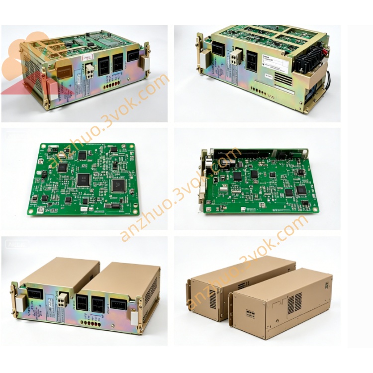
CACR-SR15BB1CS belongs to YASKAWA Yasnac VS800 full digital AC Servopack series, rated 1.5kW for 200V class industrial application. It is an OEM customized servo drive with factory pre-programmed fixed firmware, different from standard open-parameter model CACR-SR15BB1BM. Key control parameters and CN1 I/O assignment are preset and locked during factory production for exclusive matching with designated CNC machine or special automation equipment, so cross replacement with general standard servo without firmware rewrite is unavailable.
Model code breakdown: CACR stands for VS800 series servo dedicated for CNC equipment; SR means hardware supports dual command input including ±10VDC analog signal and differential pulse position signal; 15 refers to rated matching motor power 1.5kW; BB is standard universal main PCB circuit; 1 represents three-phase AC200~230V main input plus separated single-phase AC200V control power supply; CS stands for OEM customized fixed firmware version with locked partial parameters and fixed I/O definition.This drive is designed to work with specified incremental encoder Yaskawa servo motors, mainly applied on special-purpose machine tools and customized automation production lines.
2. Electrical Specifications
Main circuit input is three-phase AC200V~230V, 50/60Hz, allowable voltage variation from -15% to +10%. Control power is supplied by independent single-phase AC200~230V to avoid disturbance from main circuit fluctuation.Continuous rated output current is 11.7Arms. Overload capability: 150% rated current can run continuously for 60 seconds, 300% peak overload is limited within 3 seconds during startup.Nominal DC bus voltage ranges DC280V~DC320V, terminals P and BN are reserved for external regenerative braking resistor connection for frequent deceleration and emergency stop occasions.It adopts IGBT sine-wave PWM modulation with maximum output frequency 300Hz, protection class IP20 and only suitable for vertical cabinet installation, net weight around 3.3kg.CN2 interface is designed for standard incremental encoder without absolute encoder backup battery circuit.
3. Customized CS Version Exclusive Features
Default control mode is fixed by factory firmware, either analog speed control or differential pulse position control, users cannot switch control mode freely via parameter setting.Core parameters including position loop gain, speed loop PI gain, acceleration and deceleration time and anti-resonance filter parameters are pre-locked and cannot be modified arbitrarily on site; full auto-tuning function is restricted partially.CN1 digital input/output pins follow fixed OEM signal definition, I/O function remapping via parameters is prohibited.RS422 serial communication only supports reading real-time running data and historical fault codes; locked customized parameters cannot be uploaded or downloaded through communication line.Encoder resolution is preset for designated matching servo motor, changing other specification motor will trigger encoder fault alarm directly.
4. Environmental & Installation Requirement
Operating ambient temperature ranges from 0℃ to +55℃, storage temperature from -20℃ to +70℃. Working humidity keeps 5%~80%RH with no condensation. Derate output load when installation altitude is over 1000 meters above sea level.Anti-vibration standard: 10~55Hz, single amplitude 0.5mm. Reserve over 50mm ventilation space at top and bottom inside control cabinet for heat dissipation.Cut off all AC power and wait no less than 15 minutes for full discharge of internal DC bus capacitor before opening cover or plugging connectors; hot plug CN1 and CN2 under powered status is strictly forbidden.
5. Terminal and Connector Description
R/S/T are three-phase main AC power input terminals; U/V/W connect three-phase power cable to servo motor.P and BN terminals are used for external regenerative braking resistor wiring to consume surplus energy during rapid deceleration.CN1 is opto-isolated digital I/O port with fixed CS OEM pin assignment without editable function definition.CN2 is dedicated incremental encoder feedback socket only for original matched incremental servo motor specified by CS factory setting.Front seven-segment LED displays real-time operating condition and standard VS800 series fault codes.
6. Built-in Protection Functions
Complete protection items include overcurrent, DC bus overvoltage, DC bus undervoltage, drive overheat, encoder disconnection, motor overload and CPU abnormal protection. The latest ten fault records are permanently stored inside memory without data loss after power off or fault reset.Internal dynamic brake circuit is integrated for regular low-load deceleration; external braking resistor must be installed between P and BN under heavy cyclic load and frequent emergency stop working condition.
7. Replacement & Maintenance Guide
Only identical full model CACR-SR15BB1CS supports direct plug and play replacement. Standard CACR-SR15BB1BM or other BF/Y series servo cannot substitute directly due to different locked CS firmware and fixed I/O logic, replacement needs manufacturer to rewrite CS dedicated program.Check tightness of power wiring and CN1/CN2 connectors before startup every day; clean radiator dust every three to six months to avoid overheat shutdown caused by poor heat dissipation.Full factory parameter reset is strictly prohibited for CS model, reset operation will erase OEM preset fixed parameters and lead to abnormal machine operation.
8. Common Troubleshooting
Overheat alarm is caused by clogged radiator dust, poor cabinet ventilation or continuous overload; solve by cleaning cooling fin or reducing working load.Encoder fault arises from loose CN2 plug, damaged feedback cable or mismatched non-designated motor; check wiring and replace matched original incremental motor.Deceleration overvoltage fault can be eliminated by installing external braking resistor between P and BN terminals.Parameter write failure occurs when trying to modify CS locked core parameters, which is normal software protection instead of hardware damage.Overload alarm results from mechanical jamming or excessive payload; inspect mechanical transmission structure and cut down load accordingly.
9. Fault Code Definition
1=Overcurrent fault2=Main circuit abnormal3=DC bus overvoltage4=DC bus undervoltage5=Drive overheat6=Encoder disconnection7=Motor overloadA=CPU malfunctionC=External emergency stop activated
Get a Quote