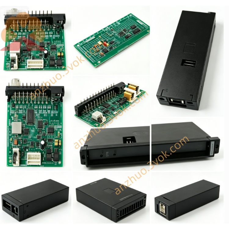
RELIANCE 805401-1S trigger pulse generation and auxiliary monitoring control PCB board
805401-1S is a trigger pulse generation and auxiliary monitoring control PCB board for RELIANCE FlexPak analog DC drive series, upgraded from base model 805401-1 with S customized specification. Original manufacturer has discontinued production, and this circuit board serves only as aftermarket replacement spare for maintenance and refurbishment of aging field DC speed control equipment. S suffix refers to surge enhanced version with optimized internal grid spike suppression circuit to adapt sites with unstable power supply and frequent voltage fluctuation. It cooperates with thyristor power module to provide phase-shift trigger signal and execute drive fault detection logic.
Description
1. Product Brief Introduction
805401-1S is a trigger pulse generation and auxiliary monitoring control PCB board for RELIANCE FlexPak analog DC drive series, upgraded from base model 805401-1 with S customized specification. Original manufacturer has discontinued production, and this circuit board serves only as aftermarket replacement spare for maintenance and refurbishment of aging field DC speed control equipment. S suffix refers to surge enhanced version with optimized internal grid spike suppression circuit to adapt sites with unstable power supply and frequent voltage fluctuation. It cooperates with thyristor power module to provide phase-shift trigger signal and execute drive fault detection logic.
2. Model Definition
805401 is fixed base part number for FlexPak drive trigger and auxiliary monitoring control card.1 stands for first generation base hardware revision of original circuit layout.S represents surge-resistant upgraded design with built-in full-range transient voltage absorption circuit and partial PCB conformal insulation coating.
3. Technical Specifications
Auxiliary control power supports 110VAC/230VAC dual input and fits global 50Hz/60Hz industrial frequency. Standard analog reference control signal is 0~±10VDC. Continuous working ambient temperature ranges from -20℃ to +58℃, applicable relative humidity 5%~93% under non-condensing condition. Overall dimension is 226mm×150mm×33mm, net weight around 0.74kg. Onboard trimming potentiometers and LED indicator lamps for trigger status, working power and fault alarm indication.
4. Interface and Communication Configuration
Gold finger edge plug connector is applied for backplane connection with drive main power base unit. External terminal blocks are reserved for analog speed reference wiring, fault dry-contact output and system interlock signal wiring. No onboard Modbus, Profibus or DeviceNet fieldbus ports, all signal transmission relies on hardwired analog and discrete wiring connection.
5. Core Functions
Produces accurate adjustable phase-shift trigger pulses to drive armature SCR rectifier module and realize continuous regulation of DC output voltage. Built-in multi-channel fault monitoring circuit collects overcurrent, abnormal power and overheat feedback signals from power unit, instantly blocks trigger output and sends interlock signal to lock drive operation once faults are triggered. Onboard adjustable potentiometers support fine tuning of trigger phase angle to match actual DC motor load features. Surge suppression design of S version reduces damage risk from instantaneous grid surge to onboard electronic components, matching main speed control board to complete full closed-loop speed regulation of DC drive system.
6. Application Scenarios
Full mechanical and electrical compatibility with standard FlexPak non-regenerative analog DC drives of low and medium power range. It is commonly used as replacement spare for overhaul of plastic extruder auxiliary drive, textile winding machine, small wire drawing equipment and metallurgical auxiliary conveyor DC speed regulation system, prioritized for workshops with unstable power grid and regular instantaneous voltage surge.
7. Operation and Maintenance Instructions
Cut off drive main AC supply and auxiliary control power, wait no less than 20 minutes for full discharge of internal capacitor residual voltage before dismounting the control board to avoid high voltage damage. Keep gold finger contact clean without dust and oxide during installation. Remove PCB surface dust with low-pressure dry compressed air in routine maintenance, organic solvent scrub on insulation coating is prohibited. Replace entire circuit board directly under abnormal trigger output, random frequent fault locking or out-of-control motor speed, local discrete component maintenance on site is not recommended. Store unused spare boards inside constant-temperature dry cabinet away from corrosive gas and violent mechanical impact.
Get a Quote