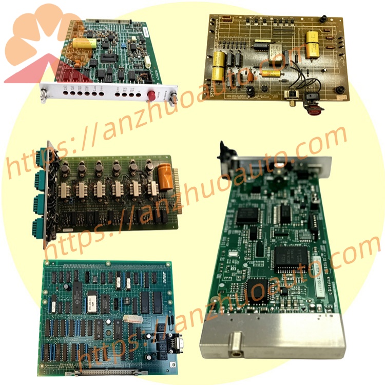
RELIANCE 803.65.00 original main control regulation circuit boardoriginal main control regulation circuit board
803.65.00 is an original main control regulation circuit board manufactured by RELIANCE Electric for FlexPak3000 series four-quadrant DC variable speed drives. It is a core plug-in obsolete spare component made with flame retardant industrial PCB and high reliability screened electronic components. As the central control unit of the whole DC drive system, this board completes closed-loop speed and current regulation as well as peripheral signal acquisition and trigger pulse output. It is widely used for faulty board replacement and equipment renovation of aging DC drive equipment on metallurgical, papermaking and plastic processing industrial production lines.
Description
1. Product Brief Introduction
803.65.00 is an original main control regulation circuit board manufactured by RELIANCE Electric for FlexPak3000 series four-quadrant DC variable speed drives. It is a core plug-in obsolete spare component made with flame retardant industrial PCB and high reliability screened electronic components. As the central control unit of the whole DC drive system, this board completes closed-loop speed and current regulation as well as peripheral signal acquisition and trigger pulse output. It is widely used for faulty board replacement and equipment renovation of aging DC drive equipment on metallurgical, papermaking and plastic processing industrial production lines.
2. Model Definition
803 is the fixed series prefix for FlexPak3000 main control board product family, defining unified backplane plug size and basic framework specification of this product line.65 represents exclusive circuit design code customized for four-quadrant regenerative DC speed control topology, corresponding to fixed internal component layout and terminal definition.00 stands for original factory baseline hardware revision without subsequent optimized upgrade modification or customized function suffix.
3. Technical Specifications
Auxiliary control input power is supplied by drive built-in auxiliary transformer. Continuous working ambient temperature ranges from -20℃ to +50℃, instantaneous peak short-time allowable temperature shall not exceed 65℃. Working relative humidity is controlled between 5% and 95% under non-condensing environment to prevent PCB damp corrosion and terminal oxidation. All analog and digital signal terminals adopt built-in TVS surge absorption and optocoupler isolation protection structure. All onboard components pass high-low temperature cycle aging and random vibration testing to adapt heavy load frequent start-stop industrial operating conditions. Overall dimension is around 265mm×158mm×42mm with approximate net weight of 1.48kg.
4. Interface and Communication Configuration
Two connection forms are equipped on this board. Gold finger edge connector is designed for plugging into drive internal backplane bus to finish internal power supply transmission and mainboard data interaction. Multiple groups of screw terminal blocks are reserved for external wiring including analog speed reference signal, digital start-stop interlock signal and fault feedback signal. The board supports native Modbus RTU communication protocol to realize data interaction with upper PLC and SCADA monitoring system, and no independent Profibus or DeviceNet expansion interface is reserved.
5. Core Functions
The board collects real-time armature current, field excitation current and motor speed feedback signals from peripheral sampling circuits, executes dual closed-loop PI operation algorithm and outputs accurate trigger pulses to control SCR thyristor rectifier module, realizing stable four-quadrant variable speed regulation of matched DC motor. Built-in self-diagnosis circuit continuously monitors abnormal operating states such as overcurrent, overvoltage, field loss and overheat. Once fault condition is detected, the unit locks trigger pulse output and sends external fault alarm signal to cut off drive power output for equipment protection. Onboard EEPROM stores all drive configuration parameters, supporting local parameter setting via operation panel and remote parameter upload or download through communication bus.
6. Application Scenarios
This main control board is specially compatible with RELIANCE FlexPak3000 four-quadrant DC speed regulators. It is commonly installed inside drive cabinets of metallurgical rolling auxiliary transmission equipment, papermaking winding and unwinding main drive, plastic extruder spindle and metal wire drawing machine. The product is applicable for indoor closed electrical cabinet installation environment of industrial workshops and frequently adopted in old production line retrofit projects keeping original drive power structure while replacing damaged core control boards.
7. Operation and Maintenance Instructions
Completely disconnect main AC input power of matched drive and wait more than 10 minutes for full discharge of residual electricity on internal capacitors before disassembly or replacement work to avoid electric shock and power device burnout. Insert gold finger fully and accurately into backplane slot during installation, and tighten all external wiring terminal screws firmly to eliminate poor contact caused by mechanical vibration. In regular maintenance period, remove accumulated conductive dust on PCB surface with dry low-pressure compressed air, and forbid high-speed airflow directly impacting tiny surface mount chips and electrolytic capacitors. Replace the whole circuit board directly when abnormal speed runaway, frequent false fault triggering or internal open/short circuit failure occurs, and on-site discrete component disassembly and repair is not recommended. Unused spare boards should be sealed and stored in dry constant-temperature warehouse away from corrosive gas and violent mechanical collision.
Get a Quote