RELIANCE 802288-46A original OEM digital logic control PCB
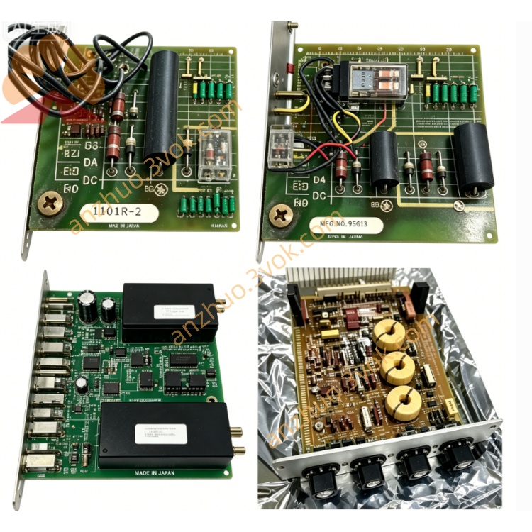
802288-46A is an original OEM digital logic control PCB developed by Reliance Electric for FlexPak3000 series DC variable speed drive, a derivative upgraded model of 802288 base series control board. It is a plug-in built-in control board inside drive cabinet with flame-retardant industrial PCB and screened electronic components, focusing on multi-channel digital interlock signal acquisition, auxiliary speed signal preprocessing and internal drive power distribution management. This discontinued spare part is widely applied for field breakdown replacement and old drive retrofitting of metallurgy, paper-making and textile production line DC drives.
2. Model Definition
Description
1. Product Brief Introduction
802288-46A is an original OEM digital logic control PCB developed by Reliance Electric for FlexPak3000 series DC variable speed drive, a derivative upgraded model of 802288 base series control board. It is a plug-in built-in control board inside drive cabinet with flame-retardant industrial PCB and screened electronic components, focusing on multi-channel digital interlock signal acquisition, auxiliary speed signal preprocessing and internal drive power distribution management. This discontinued spare part is widely applied for field breakdown replacement and old drive retrofitting of metallurgy, paper-making and textile production line DC drives.
2. Model Definition
802288 is fixed base part number of the whole PCB family, unifying PCB outline size, cabinet slot installation dimension and base circuit layout for all variant specifications within this series.46 stands for exclusive internal component layout, terminal definition and digital loop circuit configuration, differing from sibling types like 802288-45A, 802288-42.Suffix A indicates the second factory revised version with upgraded optocoupler isolation circuit and reinforced surge suppression components compared with original base 46 version, improving anti-interference performance under severe industrial EMI environment.
3. Technical Specifications
Standard working auxiliary power supply: 24VDC from drive internal control power source. Continuous operating ambient temperature: -10℃ ~ +60℃, transient peak temperature limit ≤68℃. Operating relative humidity ranges from 5% to 95% under non-condensing working condition to avoid PCB damp and terminal corrosion. All input digital channels adopt optocoupler isolation design to filter field voltage surge and noise; all onboard electronic parts pass high-low temperature cycle aging and random vibration testing for heavy-load frequent start-stop working environment. Overall dimension: approx 204mm×128mm×32mm, net weight about 0.46kg.
4. Interface and Communication Configuration
Equipped with two connection structures: onboard pin header plug connectors for internal data interconnection with drive main control board via proprietary flat ribbon cable; multiple groups of screw terminal blocks for external dry-contact interlock signal hard wiring. No built-in standard fieldbus interfaces including Modbus, Profibus, DeviceNet. All internal data transmission adopts Reliance dedicated parallel bus protocol without reserved external communication expansion ports.
5. Core Functions
Isolates, filters and converts external digital dry-contact signals including emergency stop, cabinet safety door interlock, motor thermal overload and auxiliary equipment fault protection, then transmits standardized logic signal to main control unit for drive protection shutdown control. Completes preliminary conditioning and filtering of partial tachometer analog speed feedback signal before forwarding to master control board for closed-loop speed regulation. Distributes and monitors branch auxiliary power inside drive cabinet, triggers fault feedback signal to mainboard once branch circuit overcurrent, short-circuit or undervoltage failure occurs.
6. Application Scenarios
Mainly used for fault replacement of FlexPak3000 DC drives installed on metallurgical auxiliary rolling transmission, papermaking main drag line, heavy textile spinning equipment and large CNC spindle driving unit. Suitable for closed indoor electrical cabinet installation of industrial workshop, commonly used for old production line reform projects which retain original drive power frame and only replace damaged control circuit boards.
7. Operation and Maintenance Instructions
Cut off total input power of matched drive and wait more than 5 minutes for residual capacitor electricity full discharge before disassembly to prevent electric shock and component burnout. Align pin header accurately with mainboard socket during installation and fully tighten all external wiring terminal screws to avoid loose contact caused by mechanical vibration. Keep PCB away from liquid splash and conductive dust accumulation in daily running. Clear accumulated dust with dry low-pressure compressed air during regular maintenance, prohibit high-speed airflow directly impacting tiny precision components. Replace whole circuit board directly after signal missing, intermittent abnormal operation or internal open/short fault; on-site discrete component repair is not recommended. Spare unused boards need sealed constant-temperature dry storage to avoid corrosive gas erosion and mechanical collision damage.
Get a Quote