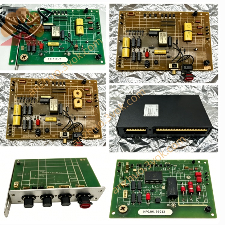
RELIANCE 801429-RC original auxiliary signal and power conditioning board
801429-RC is an original auxiliary signal and power conditioning board belonging to RELIANCE MaxPak Plus DC spindle drive series. It acts as standardized aftermarket replacement spare part for internal cabinet circuit assembly of legacy DC drive units. The board is fabricated with industrial-grade electronic components and flame-retardant substrate, fully complying with original factory electrical parameters and mechanical installation dimensions to support direct plug-in replacement during drive breakdown maintenance and old production equipment cabinet modification.
Description
1. Product Brief Introduction
801429-RC is an original auxiliary signal and power conditioning board belonging to RELIANCE MaxPak Plus DC spindle drive series. It acts as standardized aftermarket replacement spare part for internal cabinet circuit assembly of legacy DC drive units. The board is fabricated with industrial-grade electronic components and flame-retardant substrate, fully complying with original factory electrical parameters and mechanical installation dimensions to support direct plug-in replacement during drive breakdown maintenance and old production equipment cabinet modification.
2. Model Definition
801429 is the unified base part number for this series of drive auxiliary circuit assemblies, representing fixed core circuit layout and overall outline specification of the entire product family.RC is customized function suffix standing for rapid clamp surge protection plus regulated control power design, equipped with fast-response surge absorbing loop and stabilized auxiliary control power circuit, which differs from SC, VF, RE and other derivative versions under the same base part code.
3. Technical Specifications
The board matches the standard internal control loop rated voltage of MaxPak Plus DC drives and tolerates conventional industrial power supply fluctuation range. Continuous rated operating ambient temperature ranges from -10℃ to +65℃, instantaneous peak short-term working temperature is limited below 72℃. Allowable working relative humidity is 5% to 95% under non-condensing condition to prevent pin corrosion and insulation damage of internal circuits. All built-in electronic components pass high-low temperature aging and anti-vibration screening to adapt frequent start-stop and fluctuating load working environment of on-site industrial transmission equipment.
4. Interface and Communication Configuration
Only screw-type hard-wiring terminal blocks are configured on the board, divided into auxiliary power access terminals and analog/digital signal wiring terminals. No embedded fieldbus communication ports such as Modbus, Profibus or DeviceNet are arranged. All power distribution and control signal transmission are finished by hard wiring following RELIANCE original factory wiring diagram, and terminal layout is designed to match reserved wiring space of standard MaxPak Plus drive cabinet.
5. Core Functions
It supplies stabilized branched auxiliary power for internal drive sensing components and small auxiliary control circuits. Exclusive RC fast clamping circuit rapidly absorbs instantaneous surge voltage from field wiring and power grid fluctuation to isolate impact damage for drive main control motherboard. Built-in signal filtering circuit eliminates external high-frequency electromagnetic interference to improve stability of closed-loop speed feedback signals. Meanwhile it serves as intermediate signal transit bridge to reorganize transmission routes between main control board and external field detection devices.
6. Application Scenarios
This circuit board is mainly used for fault replacement and maintenance upgrade of aging MaxPak Plus spindle drive systems installed on CNC spindle equipment, papermaking transmission lines, metallurgical auxiliary rolling machinery and heavy textile spinning equipment. It fits conventional indoor workshop electrical cabinet installation environment and is widely applied in old equipment renovation projects retaining original RELIANCE drive cabinet and main hardware structure.
7. Operation and Maintenance Instructions
Cut off the whole system main power supply completely before installation, inspect all terminals for oxidation, looseness and dust accumulation and clean residual impurities to guarantee stable wiring contact. Perform wiring strictly in accordance with factory original circuit schematic and prohibit reversed polarity connection to avoid permanent internal circuit burnout. In regular daily maintenance, power off periodically and clear accumulated surface dust with dry compressed air to prevent dust-caused short-circuit faults. Regularly monitor running temperature under full-load condition and stop equipment for inspection once abnormal overheating or continuous signal drift occurs. Replace the whole board directly upon internal open/short-circuit failure, on-site split repair of discrete internal components is not recommended. Spare boards shall be stored in dry constant-temperature warehouse away from corrosive gas and violent mechanical collision.
Get a Quote