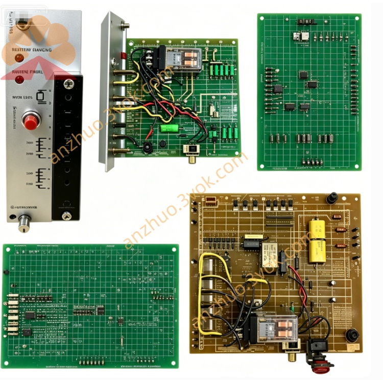
RELIANCE 770-90-00 rack mounted auxiliary power supply module
770-90-00 is a rack mounted auxiliary power supply module belonging to RELIANCE AutoMax control system series. It is designed for installation inside AutoMax control rack and provides multiple groups of stable DC working power for rack CPU board, signal acquisition modules and communication cards. The internal PCB is covered with protective conformal coating to resist damp, dust and electromagnetic interference in industrial cabinet environment. This product is widely used as replacement spare part for damaged original power modules during on-site control cabinet maintenance and old automation system renovation.
Description
1. Product Introduction
770-90-00 is a rack mounted auxiliary power supply module belonging to RELIANCE AutoMax control system series. It is designed for installation inside AutoMax control rack and provides multiple groups of stable DC working power for rack CPU board, signal acquisition modules and communication cards. The internal PCB is covered with protective conformal coating to resist damp, dust and electromagnetic interference in industrial cabinet environment. This product is widely used as replacement spare part for damaged original power modules during on-site control cabinet maintenance and old automation system renovation.
2. Model Definition Explanation
770 stands for the general module series code of RELIANCE AutoMax rack accessory product line. 90 represents fixed internal circuit design and output specification classification of auxiliary power supply units. 00 is standard factory basic version code with no customized hardware alteration on internal component configuration.
3. Technical Specifications
The module obtains input alternating current power from cabinet internal auxiliary power loop. Operating ambient temperature ranges from -10 degrees Celsius to 55 degrees Celsius, extra forced ventilation cooling is required for continuous full-load running above 45 degrees Celsius. Working environmental relative humidity shall not exceed 90 percent under non-condensing condition. It outputs several isolated DC voltage specifications for different rack modules, with built-in overvoltage, overcurrent and short-circuit protection circuits which cut off output automatically once abnormal load emerges to avoid subsequent component burnout. The overall dimension conforms to unified AutoMax rack slot mounting standard.
4. Interface and Communication Configuration
Rear golden finger connects with rack backplane for power input and fixed mechanical positioning. Front panel is equipped with screw type terminal blocks for auxiliary power input wiring and spare test terminals. This is a dedicated power supply unit without built-in fieldbus or serial communication circuit, no independent communication wiring terminals and no reserved expansion slots for external communication adapters. All power distribution is completed through backplane bus inside control rack.
5. Core Functions
Converts input AC power into multiple isolated stable DC power outputs to sustain normal operation of all plug-in modules on AutoMax control rack. Internal filter circuits restrain power grid surge and ripple fluctuation to improve whole control system anti-interference performance. Integrated hardware protection mechanisms rapidly shut down output under overload, short-circuit or abnormal input voltage conditions to protect expensive CPU and functional modules on the rack from irreversible damage.
6. Application Scenarios
It is installed in standard RELIANCE AutoMax PLC control cabinets and matched with supporting digital control modules and field DC drive equipment. Main application fields cover metallurgical rolling production line centralized control, textile assembly line drive control, printing machinery linkage control and large fan & water pump automation control in chemical and building material industries, serving as essential spare part for regular equipment maintenance and fault replacement.
7. Operation and Maintenance Instructions
Completely cut off the total input power of control cabinet and lock power source before plugging out or installing the module to prevent hot plug induced circuit damage. Carry out power-off dust cleaning for PCB surface, golden finger and internal heat dissipation parts every three to six months based on on-site dust concentration. Regularly inspect aging condition of internal electrolytic capacitors and fastening status of wiring terminals. Stop system operation and inspect internal components once abnormal overheating or intermittent power supply failure occurs, prohibit long-term overloaded operation beyond rated output parameters.
Get a Quote