RELIANCE 770.90.21 original Automax Autobus interface card
770.90.21 is an original Automax Autobus interface card developed by RELIANCE Electric, belonging to the 770.90 series rack-mounted automation module platform. It adopts standard plug-in chassis structure for backplane slot installation, specially designed to realize data interaction between Automax main controller and field drive units via proprietary Autobus field bus protocol. The circuit board is coated with anti-corrosion insulating paint to adapt to harsh industrial cabinet environment, widely used as core communication spare part for RELIANCE DC speed control system and Automax PLC control rack renovation and fault replacement.
Description
1. Product Introduction
770.90.21 is an original Automax Autobus interface card developed by RELIANCE Electric, belonging to the 770.90 series rack-mounted automation module platform. It adopts standard plug-in chassis structure for backplane slot installation, specially designed to realize data interaction between Automax main controller and field drive units via proprietary Autobus field bus protocol. The circuit board is coated with anti-corrosion insulating paint to adapt to harsh industrial cabinet environment, widely used as core communication spare part for RELIANCE DC speed control system and Automax PLC control rack renovation and fault replacement.
2. Model Definition Explanation
770 stands for RELIANCE Automax series general-purpose communication module product code. The middle numeric 90 represents unified hardware base circuit group of this series interface board. Suffix 21 is the version code for Autobus dedicated communication customized specification, distinguishing from standard power version 770.90.00 with different internal bus circuit layout and terminal definition.
3. Technical Specifications
Working power is supplied by rack backplane DC bus inside Automax control cabinet. Rated operating ambient temperature ranges from -10 degrees Celsius to 55 degrees Celsius; continuous full-load running above 45 degrees Celsius requires forced cabinet air circulation. Working environment relative humidity is limited below 90 percent without condensation. Built-in hardware overvoltage, overcurrent and surge protection circuit to resist instantaneous grid interference. Overall mechanical dimension follows industry standard 6U rack card specification for unified slot insertion installation.
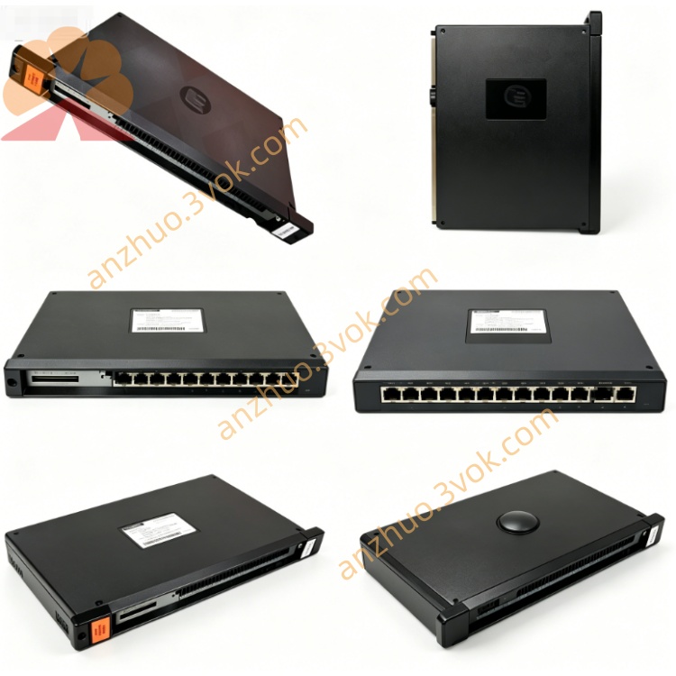
4. Interface and Communication Configuration
Rear side realizes power supply and internal backplane data exchange through golden finger plug connected with cabinet rack backplane. Front panel is equipped with multi-channel screw terminal groups, among which part terminals are used for Autobus field bus wiring to connect on-site DC drive modules, remaining reserved terminals serve for auxiliary signal wiring. Core communication relies on proprietary Autobus industrial bus protocol to finish cyclic data reading and instruction transmission between master controller and field drivers, no external standard fieldbus expansion interface is reserved.
5. Core Functions
Act as intermediate data transfer gateway between Automax main control CPU and distributed on-site variable speed drive equipment. Complete real-time collection of drive operating status, fault codes and running parameter feedback, meanwhile forward speed setting, start-stop control commands from upper controller to corresponding drive units. Built-in communication fault self-diagnosis logic to upload bus disconnection or short-circuit abnormal information to main control system for alarm prompt, ensuring stable closed-loop control of whole automation system.
6. Application Scenarios
Mainly assembled in RELIANCE Automax series PLC control cabinet, matched with brand E5800/E6800 series heavy-duty DC drives. Widely deployed on metallurgical rolling production line transmission control, large extruder drive control system, mine belt conveyor master control and industrial high-power fan drive control projects, serving as essential replacement spare during equipment overhaul and drive system upgrading in metallurgy, heavy machinery and chemical industries.
7. Operation and Maintenance Instructions
Cut off total cabinet main power and execute locking safety procedure before pulling out or inserting the module to avoid plugging with live current causing circuit burnout. Clean accumulated dust on circuit board and golden finger contact surface every four to six months according to on-site dust density. Regularly check tightness of front terminal wiring to prevent poor contact triggering intermittent communication failure. Replace the module immediately once persistent bus communication interruption or frequent controller alarm occurs after troubleshooting external wiring faults, forbid long-term abnormal running with defective communication board.
Get a Quote