RELIANCE 73126-6R VSS series reactor and matched braking signal interface circuit board
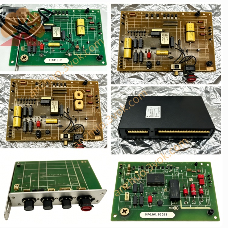
73126-6R is a VSS series reactor and matched braking signal interface circuit board manufactured by RELIANCE Electric, specially designed for the brand’s classic DC drive speed control systems. This integrated unit combines inductive reactor components and transistor-type braking logic control circuit on one single assembly, installed inside the DC drive cabinet for DC bus filtering and dynamic braking status signal conversion. Adopting industrial grade enameled wire winding and anti-corrosion PCB substrate, it resists vibration and electromagnetic interference from harsh industrial environments, mainly applied as aftermarket replacement spare part for aged or faulty original reactor modules on on-site drive equipment maintenance.
Description
1. Product Introduction
73126-6R is a VSS series reactor and matched braking signal interface circuit board manufactured by RELIANCE Electric, specially designed for the brand’s classic DC drive speed control systems. This integrated unit combines inductive reactor components and transistor-type braking logic control circuit on one single assembly, installed inside the DC drive cabinet for DC bus filtering and dynamic braking status signal conversion. Adopting industrial grade enameled wire winding and anti-corrosion PCB substrate, it resists vibration and electromagnetic interference from harsh industrial environments, mainly applied as aftermarket replacement spare part for aged or faulty original reactor modules on on-site drive equipment maintenance.
2. Model Definition Explanation
73126 stands for fixed base part number representing standard winding parameter and circuit layout of VSS type reactor series; the middle digit 6 corresponds to rated inductance specification and matching drive power grade; suffix R represents revised production version with optimized internal winding insulation and switching transistor peripheral circuit for improved overload durability compared to non-revision original version.
3. Technical Specifications
Rated applicable DC bus working voltage is above 50VDC, operating ambient temperature ranges from -10℃ to 55℃, continuous running above 45℃ needs auxiliary cabinet air cooling to avoid insulation aging. Allowed relative working humidity is less than 90% without dew condensation. Built-in inductance coil suppresses DC bus current ripple while onboard transistor circuit bears rated switching control load, equipped with indicator LED that lights up when braking loop current IB exceeds preset threshold value. The whole assembly is designed for embedded cabinet installation with no open-air mounting capability, internal structure integrates passive filtering components and non-contact solid-state switching elements.
4. Interface and Communication Configuration
All external connections adopt fixed terminal pin wiring mode, split into DC bus input terminals, braking current sampling terminals and S1-2 switching signal output terminals between terminal 1 negative pole and terminal 2 positive pole. No native fieldbus communication chip or digital communication interface is pre-installed at factory. All braking state feedback signals are transmitted via hard-wire switching contact output without remote digital data transmission function, no reserved expansion slot for external communication adapter installation.
5. Core Functions
The reactor part filters fluctuation ripple current on drive DC bus to stabilize bus voltage and reduce harmonic impact on main power thyristor components. The onboard control circuit samples real-time braking loop current and DC bus voltage; when DC voltage exceeds 50VDC and braking current IB equals zero, internal solid-state switch S1-2 keeps closed; when braking current rises above set value or DC bus voltage drops below 50VDC, the switch turns open to feed braking operating status signal back to drive main control board. It cooperates with main control logic to complete dynamic braking protection and running status monitoring for DC motor speed regulation system.
6. Application Scenarios
It is internally assembled within RELIANCE standard DC speed drive units, widely used for metallurgical rolling line drive motors, textile production main transmission equipment, industrial printing machinery, large fan and water pump DC drive systems. It serves as core replacement spare part during production line equipment overhaul, old drive renovation and on-site reactor fault maintenance across machinery manufacturing, chemical and building material industries.
7. Operation and Maintenance Instructions
Completely cut off the whole drive’s main incoming power before disassembly and wiring to prevent electric shock and component breakdown, strictly follow terminal polarity marking for wiring connection. Perform power-off dust clearance for coil surface and PCB component gaps every three to six months based on site dust concentration to avoid accumulated dust triggering insulation short circuit. Regularly check coil enamel layer for damage and solder joints for cold solder or loosening. Immediately shut down equipment once abnormal LED continuous alarm or frequent braking fault occurs, inspect internal winding and switching transistor damage before system restart, prohibit long-term continuous overload operation beyond rated voltage and current range.
Get a Quote