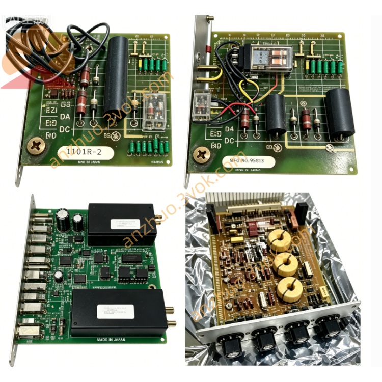
RELIANCE 705330031R dedicated drive control printed circuit board
705330031R is a dedicated drive control printed circuit board from RELIANCE Electric, customized for the brand’s classic DC drive series. This circuit board acts as the central signal control component inside the drive cabinet, responsible for closed-loop speed regulation calculation, feedback signal acquisition and power trigger signal distribution. Constructed with industrial standard electronic parts and anti-interference PCB coating, it can cope with industrial environments featuring vibration, temperature variation and electromagnetic interference, mainly used for original unit replacement and field maintenance spare parts of outdated RELIANCE DC speed control equipment.
Description
1. Product Introduction
705330031R is a dedicated drive control printed circuit board from RELIANCE Electric, customized for the brand’s classic DC drive series. This circuit board acts as the central signal control component inside the drive cabinet, responsible for closed-loop speed regulation calculation, feedback signal acquisition and power trigger signal distribution. Constructed with industrial standard electronic parts and anti-interference PCB coating, it can cope with industrial environments featuring vibration, temperature variation and electromagnetic interference, mainly used for original unit replacement and field maintenance spare parts of outdated RELIANCE DC speed control equipment.
2. Model Definition Explanation
705330031 is the fixed base part number representing standard circuit layout and functional specification of this control board series. The trailing suffix R stands for revised updated version, with optimized partial peripheral circuits and component matching compared to the base non-revision model to improve operational stability and fault resistance in complicated field working conditions.
3. Technical Specifications
This board runs on designated DC auxiliary power supplied by the internal power module of the drive unit. Its permissible working ambient temperature ranges from -10℃ to 55℃, and performance derating is required for continuous operation above 45℃. It supports analog command input signals of 0–10V voltage or 4–20mA current, together with multi-channel dry contact digital input signals for start-stop and direction control. The applicable relative humidity is below 90% without dew condensation, and internal circuits contain hardware threshold detection for overcurrent, overvoltage and overheating protection signals. It is designed for inner cabinet embedded installation with no exposed outdoor application capability.
4. Interface and Communication Configuration
All external signal connections adopt fixed pin header hard-wire terminals, including power supply pins, analog input and output terminals, digital signal terminals and pulse output terminals connecting to the thyristor power unit. No native onboard fieldbus communication circuit is equipped at factory delivery. All data exchange with external PLC or upper-level control devices is finished through hard wiring, and no spare expansion slots are reserved for additional communication adapter modules.
5. Core Functions
The board gathers real-time armature and field feedback signals from the DC motor and power loop, completes closed-loop speed computing according to external setpoint instructions, and outputs trigger pulses to control the conduction angle of the power thyristor so as to adjust motor rotating speed stably. It continuously monitors the full drive system’s running parameters, outputs external fault alarm signals and locks drive operation once operational parameters go beyond safe preset limits. Besides, it preserves core operational parameter settings and supports on-site parameter fine-tuning via peripheral terminal configuration.
6. Application Scenarios
It is internally fitted inside RELIANCE standard DC speed regulators, widely deployed in metallurgical rolling equipment, textile production line drive systems, printing machinery, industrial water pump and fan speed control units. It serves as core replacement spare part for broken original control boards during production line upgrade renovation and equipment breakdown maintenance across machinery manufacturing, chemical and construction material industries.
7. Operation and Maintenance Instructions
Cut off the whole drive’s input power fully before mounting or dismounting the circuit board to avoid short-circuit damage to electronic components, and follow original terminal definition strictly during wiring. Perform power-off dust cleaning on PCB surface and component gaps every three to six months based upon on-site dust and corrosive gas concentration. Regularly inspect onboard electrolytic capacitors for liquid leakage and soldering points for virtual welding. Shut down equipment power promptly when abnormal speed fluctuation or recurring fault alarms emerge, complete component inspection and damage troubleshooting before equipment restart, and prohibit long-time operation under abnormal overvoltage or overcurrent conditions.
Get a Quote