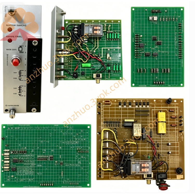
RELIANCE 705315002R proprietary control circuit board
705315002R is a proprietary control circuit board produced by RELIANCE Electric, specially designed as core control spare part for the company’s legacy DC drive and variable speed drive assemblies. This printed circuit board undertakes signal sampling, logic operation and drive pulse transmission for the whole speed regulating system, adopting industrial grade component layout with anti-vibration and anti-electromagnetic interference structural design. It is mainly used for original equipment matching and after-sales replacement maintenance of old generation RELIANCE industrial drive equipment in field automation systems.
Description
1. Product Introduction
705315002R is a proprietary control circuit board produced by RELIANCE Electric, specially designed as core control spare part for the company’s legacy DC drive and variable speed drive assemblies. This printed circuit board undertakes signal sampling, logic operation and drive pulse transmission for the whole speed regulating system, adopting industrial grade component layout with anti-vibration and anti-electromagnetic interference structural design. It is mainly used for original equipment matching and after-sales replacement maintenance of old generation RELIANCE industrial drive equipment in field automation systems.
2. Model Definition Explanation
705315002 serves as the fixed base part number of this series control board, corresponding to standardized circuit schematic and hardware layout of the core signal control unit. The suffix R indicates revised upgraded revision of the original circuit design, with partial component and circuit optimization compared to non-R standard version to enhance environmental adaptability and running stability.
3. Technical Specifications
The board works with auxiliary DC power supplied by the drive’s internal auxiliary power module, rated operating ambient temperature spans from -10 degrees Celsius to 55 degrees Celsius, performance derating is needed under continuous high temperature over 45 degrees Celsius. It accepts multi-channel analog speed command signals ranging 0 to 10V or 4 to 20mA and digital switch input signals from external control terminals. Internal hardware integrates overcurrent, overvoltage signal detection loop, and carries built-in fault signal conversion circuit. Designed for cabinet interior installation with applicable environmental humidity below 90 percent non-condensing.
4. Interface and Communication Configuration
All external connections adopt pin header terminal hard wiring mode, including power supply pin terminals, analog input/output terminals, digital signal terminals and pulse output terminals connecting to power trigger unit. No onboard integrated fieldbus communication circuit by factory default, data interaction with external PLC and upper control equipment fully relies on hardwire signal wiring. No reserved expansion slots for optional communication expansion modules.
5. Core Functions
It collects real-time operating feedback signals from motor and power unit, processes speed closed-loop calculation according to external given speed instructions, outputs control pulses to drive power semiconductor components to realize stable motor speed regulation. It monitors operating state parameters of the whole drive system in real time, triggers corresponding fault locking and alarm signal output once abnormal parameters exceed preset threshold values. Meanwhile it completes parameter storage for basic running settings of the drive and supports local parameter setting via peripheral potentiometer or terminal signal configuration.
6. Application Scenarios
Primarily applied inside RELIANCE DC speed controllers installed on metallurgical rolling machines, textile production line transmission equipment, industrial fans and water pump drive units. Widely used as replacement spare part for aged or damaged original control boards during production line technical transformation and equipment fault maintenance in machinery processing, chemical and building materials manufacturing industries.
7. Operation and Maintenance Instructions
Complete power cut-off operation before disassembly and installation to prevent accidental circuit short and component burnout, strictly follow original terminal definition for wiring connection. Conduct regular power-off dust removal on board surface and component gaps every three to six months based on on-site dust and corrosive gas level. Regularly check for electrolyte leakage of on-board electrolytic capacitors and loose solder joints. Cut off system power immediately when drive runs with irregular fault alarms or unstable speed, inspect the circuit board for damaged electronic components before restarting the whole equipment, avoid long-term operation under severe overvoltage and overcurrent working conditions.
Get a Quote